


160
Chapter 5
BIOS Recovery by Crisis Disk
BIOS Recovery Boot Block:
BIOS Recovery Boot Block is a special block of BIOS. It is used to boot up the system with minimum BIOS
initialization. Users can enable this feature to restore the BIOS firmware to a successful one once the previous
BIOS flashing process failed.
BIOS Recovery Hotkey:
The system provides a function hotkey:
Fn+Esc
, for enable BIOS Recovery process when system is powered
on during BIOS POST. To use this function, it is strongly recommended to have the AC adapter and Battery
present. If this function is enabled, the system will force the BIOS to enter a special BIOS block, called Boot
Block.
Steps for BIOS Recovery from USB Storage:
Before doing this, prepare the Crisis USB key. The Crisis USB key could be made by executing the Crisis Disk
program in another system with Windows 7 OS.
Follow the steps below:
1.
Format the USB storage disk using the Fast Format option.
2.
Save ROM file (file name:
NEW75x64.fd
) to BIOS.FD in the root directory. Make sure that there is no
other BIOS file saved in the same directory.
3.
Plug USB storage into USB port.
4.
Press
Fn + ESC
button then plug in AC power.
5.
Press
Power
button to initiate system CRISIS mode.
When CRISIS is complete, the system auto restarts with a workable BIOS.
6.
Update the latest version BIOS for this machine by regular BIOS flashing process.
Summary of Contents for ASPIRE 5251
Page 6: ...VI...
Page 10: ...X Table of Contents...
Page 34: ...24 Chapter 1...
Page 52: ...42 Chapter 2...
Page 76: ...66 Chapter 3 5 Lift the Speaker clear of the Upper Cover...
Page 78: ...68 Chapter 3 5 Lift the Right Speaker Module clear of the device...
Page 84: ...74 Chapter 3 5 Lift the USB board clear of the device...
Page 90: ...80 Chapter 3 11 Disconnect the Bluetooth to mainboard cable...
Page 92: ...82 Chapter 3 4 Carefully lift the Thermal Module clear of the Mainboard...
Page 103: ...Chapter 3 93 7 Disconnect the LVDS cable from the panel...
Page 105: ...Chapter 3 95 5 Lift the microphone set and cable clear of the LCD cover...
Page 121: ...Chapter 3 111 5 Connect the fan cable...
Page 124: ...114 Chapter 3 6 Connect the LVDS cable to the mainboard 7 Connect the microphone cable...
Page 127: ...Chapter 3 117 4 Connect the USB cable to the mainboard and lock the connector...
Page 130: ...120 Chapter 3 4 Replace the FFC and press down as indicated to secure it to the Upper Cover...
Page 146: ...136 Chapter 3...
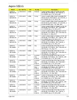
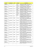
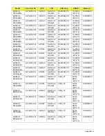
Page 175: ...Chapter 6 165 Aspire 5251 5551G 5551 FRU List...
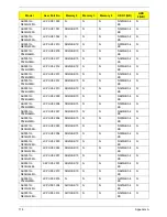
Page 176: ...166 Chapter 6 Screw List...
Page 177: ...Chapter 6 167...
Page 206: ...196 Appendix C...
Page 210: ...200...


