3 System upgrade
48
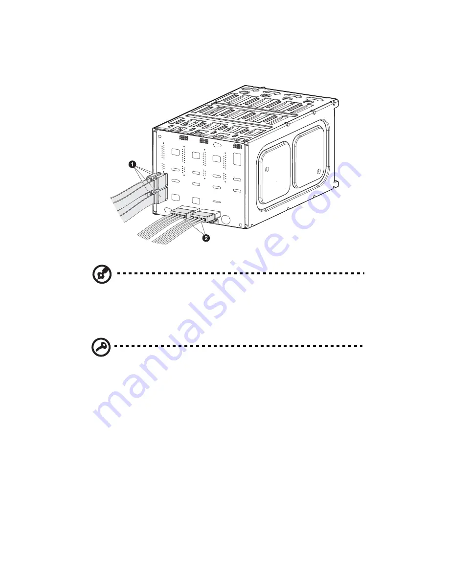
(2) Attach the system’s power cable to the SATA power cable
connector on the backplane
(2)
.
Note:
The SATA RAID backplane data cables must be installed and
removed in the following order: SATA0, SATA1, SATA2, and
SATA 3.
6
Observe the post-installation instructions described on page 36.
Important:
When you are detaching the hot-plug cage from the
chassis, make sure to first remove all hard disks from their carriers.
For instructions, see “Installing an additional hard disk into the
hot-plug HDD cage carrier” on page 53.
Summary of Contents for Altos G5350
Page 1: ...Acer Altos G5350 Series User s Guide ...
Page 10: ...x ...
Page 11: ...1 System tour ...
Page 31: ...21 5 4 pin power cable connector 6 I2 C bus interface connector No Code Description ...
Page 32: ...1 System tour 22 ...
Page 33: ...2 System setup ...
Page 43: ...3 System upgrade ...
Page 88: ...3 System upgrade 78 ...
Page 89: ...4 BIOS setup ...
Page 123: ...113 Save Changes Saves changes made in the BIOS setup Parameter Description ...
Page 124: ...4 BIOS setup 114 ...
Page 125: ...5 Troubleshooting ...
Page 136: ...5 Troubleshooting 126 ...
Page 137: ...Appendix A System management utility ...
Page 144: ...Appendix A System management utility 134 ...
Page 145: ...Appendix B Acer Altos G5350 rack installation guide ...
Page 146: ...This appendix shows you how to set up the Altos G5350 server in a rack mount configuration ...
Page 161: ...Appendix C SCSI RAID configuration ...
Page 162: ...This appendix shows you how to create a RAID volume in your SCSI drives ...


