background image

Installation Manual  I  Installation

12

MP4010-1903

3.10 Ventilation

DO  NOT  connect  Drain  or  Vent  lines  on  multiple                                                                       

         appliances. Each appliance should have its own dedicated  
         drain and vent. 

The steam vent is provided with a 45 ° elbow. The steam  

          vent must not be obstructed. An obstruction will prevent  
          correct operation of the steamer. 

Applicable federal, state and/or local plumbing codes will  

         dictate when and if a hood is required. 

3.10.1 Steam Vent Extension

When adding anything to the vent on the Evolution steamer, 
care must be taken to prevent doing anything that puts a back 
pressure on the steamer. Back pressure on the steamer may 
interfere with the pressure switch that controls the heaters. 
When the pressure switch senses pressure in the steamer 
that is 0.5” of water column or more, it turns the heaters off. 
Therefore, anything on the vent putting a pressure of just 0.5” 
water column on the steamer turns the heaters off and prevents 
them from coming on again until the pressure is relieved. 
Intermittent operation of the steamer can often be traced to 
restrictions, low spots or a plugged condensate drain in the vent 
fitting assembly.

To prevent putting a back pressure on the steamer, vent piping 
should have no restrictions and no low spots where water can 
accumulate. Ventilation piping can be directed upwards toward 
hoods or downward towards floor drains. Slightly different 
approaches are required for each application.
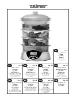
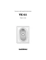
FIGURE 12

18” - 36” Long = 3/4” Diam-
eter brass pipe (both ends 
threaded)
45 ° Elbow = 3/4” Diameter 
brass pipe (both ends female)

6” - 10” Long - 3/4” Diameter 
brass pipe (both ends threaded 
male)

 Extension Sloping Upward (FIGURE 12)

1.  Use nominal ¾” copper, brass or stainless steel to prevent 

flow restrictions. Larger inside diameter (ID) can be used also 

2.  Pipe should slope upward a 1/4” per foot from the steamer 

vent toward a vent hood to allow water condensing in it to 
run back to the steamer and down the drain line. Minimum 
recommended slope is ¼” per foot of hose length. 

3.  Use rigid pipe rather than flexible tubing or hose to prevent 

dips or sags in the pipe that may collect water. A puddle 
of water in the piping just ½” deep will cause the steamer 
to malfunction. Recommended pipe materials are rigid ¾” 
copper tubing (7/8” OD) or brass/ 18-8 stainless steel pipe 
(3/4 NPT or larger). Pipe hangers or pipe supports should be 
used every six feet to prevent long runs from sagging. 

4.  A pipe union should be installed next to the steamer to 

permit the vent to be easily disconnected. This allows the 
steamer to be easily moved for servicing. 

5.  Total length of extended vent piping should not exceed 15 

feet.

Summary of Contents for EVOLUTION Series

Page 1: ...installation initial field start up and complete the equipment adjustments described in this manual IMPORTANT WARRANTY INFORMATION WARRANTY REGISTRATION STARTUP FORM INSIDE THIS MANUAL MUST BE REMOVED...

Page 2: ...GENERAL INFORMATION PAGE 5 INSTALLATION PAGE 7 OPERATION USE PAGE 14 OPERATION CLEANING PAGE 18 TROUBLESHOOTING PAGE 21 SERVICE PAGE 22 PREVENTATIVE MAINTENANCE CHECKLIST PAGE 23 WARRANTY PAGE 24 DOC...

Page 3: ...e do not attempt to operate this appliance Improper installation adjustment alteration service or maintenance can cause property damage injury or death Read the installation operating and maintenance...

Page 4: ...ns Name Technicians Email Additional Info 1 Is the steamer being installed at an altitude greater than 2 000 feet Tick Box 2 Is the steamer level Tick Box 3 Is the wall receptacle positioned in a low...

Page 5: ...n less YES NO Type of NEMA Plug Tick One Tick One L6 30P 208 240V 6kW L16 20P 480V 14kW L15 30P 208 240V 10kW IEC 60309 2 230 415V 15 50P 208 240V 15kW 15 Does the Low Water Light and Alarm turn OFF o...

Page 6: ...used here draw attention to activities that may influence safety health protection and the necessity for servicing They help you to prevent problems and the advice will make your work easier WARNING I...

Page 7: ...the base model E Electric B is the size of the unit 6 pan CCC is the supply Voltage D is the number of phases 1 or 3 E is the control series D Manual Fill E Autofill F is the energy input G is the ti...

Page 8: ...ult in performance faults Only professional installation of the device guarantees it high quality operation Check proper setting of the equipment by placing a hotel pan filled with water inside the st...

Page 9: ...ounting hole into the Evolution and tighten securely 4 Once the bottom steamer has been installed carefully lift and place the top Evolution steamer on the horizontal mounting brackets ensuring that t...

Page 10: ...d must be filled throughout the cooking process to assure consistent cook times Do not use the Low Water Indicator as your indication that this steamer requires water as this actually turns off the he...

Page 11: ...pplied with single or 3 phase 3 For use on individual branch circuit only 4 Do not connect to a circuit operating at more than 150V to ground 5 Dimensions outside brackets are inches in brackets are m...

Page 12: ...e steamer If hot is used temperature must be less than 180 F The hose must not be sharply bent kinked or twisted If the steamer is close to a wall use a right angle fitting to prevent kinking the hose...

Page 13: ...ng should have no restrictions and no low spots where water can accumulate Ventilation piping can be directed upwards toward hoods or downward towards floor drains Slightly different approaches are re...

Page 14: ...e steamer vent to a floor drain to allow water condensing in it to run unimpeded into the floor drain 3 For downward sloping extension to a floor drain ONLY ID or larger reinforced silicone hose auto...

Page 15: ...brushes metal scouring pads to clean the cooking chamber bottom 4 1 Operation Introduction The AccuTemp Evolution steamer uses the time proven method of cooking with steam Once the cooking time expire...

Page 16: ...lation Manual I Operation 15 MP4010 1903 OPERATOR DISPLAY COOK or HOLD DISPLAY TEMPERATURE OVER TEMPERATURE LAMP HIGH WATER LAMP LOW WATER LAMP SET TIMER INCREASE VARIABLE DECREASE VARIABLE ON OFF FIG...

Page 17: ...the steamer The display will indicate PrE while in Cook Mode and the temperature while in the Hold Mode 2 Once the steamer is preheated and ready to cook the display will indicate the COO Cook Mode or...

Page 18: ...food into the cooking chamber Shut the door 3 Food will be held at the preset holding temperature The factory default setting is set at 180 F 4 Depress the DISP TEMP button to display the current cook...

Page 19: ...condensate tray with a clean cloth FIGURE 19 Clean the door gasket inside of door and front face of the cooking chamber Clean water sensors with a non metallic cleaning pad Wipe down corners of cooki...

Page 20: ...of the steam collector align the 4 retaining fasteners and hand tighten then install the pan rails and the condensate tray Leave the door open overnight NOTE The steamer will not operate without the...

Page 21: ...activate the chromium oxide passive layer 8 Always rinse the unit with clean water and dry with the steamer door and drain valve open 4 7 5 How to to Protect Stainless Steel All materials used in manu...

Page 22: ...cooking cabinet 5 4 Steamer Does Not Heat If the operators display doesn t light up see Section 5 1 Verify the steamer door is closed as the unit will not heat when the door is open 5 5 Steam Comes Ou...

Page 23: ...ducts Inc Technical Service Department or the service call may not be covered by the limited warranty WARNING Only an AccuTemp Products Inc Authorized Service Personnel or Representative must perform...

Page 24: ...stand casters Monthly Inspect AC power cord for degradation or bare wires Replace if defective or suspect X Inspect door gasket for cuts and degradation Replace if damaged We suggest replacing once a...

Page 25: ...s or workmanship provided the service agency has received advance approval from AccuTemp factory service to perform the repair or replacement This warranty includes travel time not to exceed two hours...

Page 26: ......

Page 27: ...AccuTemp Product Inc Technical Customer Support Technician is available Monday thru Sunday 7 00am to 7 00pm EST 800 480 0415 or 260 469 3040 Phone 800 480 0415 or 260 469 3040 Email service accutemp...

Reviews: