background image

Installation Manual  I  Installation

11

MP4010-1903

3.9 Connected Model - Additional Connections 

3.9.1 Supply Water Line (FIGURE 11)

The installation of the water connection to the appliance is 

the responsibility of the owner and or installer.

 An inlet strainer in water inlet must be used, removal of 

strainer voids steamer warranty.

The installation of this appliance should comply with all 

applicable federal, state or local plumbing codes.

The installation requires a check valve (or other approved 

anti-back flow/ anti-siphon device) in all supply lines in accor-
dance with and as required by local, state and national health, 
sanitation and plumbing codes. AccuTemp does NOT provide a 
check valve with the steamer.

• 

Design the water supply line so the unit can be moved for 
service. Install a manual water shutoff valve between the 
water supply line and the steamer supply line.

• 

A reinforced rubber or braided stainless steel appliance 
hose rated for the temperature and pressure of the 
water supply with a 3/4” garden hose type connection is 
required.

• 

The Garden Hose Thread (GHT) connector used must 
be suitable for potable water

• 

Do not apply pipe thread sealant to GHT 
connections.

• 

Either hot or cold water can be connected to the 
steamer. If hot is used, temperature must be less 
than 180°F. 

• 

The hose must not be sharply bent, kinked or twisted.

• 

If the steamer is close to a wall, use a right angle fitting to 
prevent kinking the hose

• 

The Auto-Fill Valve has a maximum water supply pressure 
of 60 psi. If stream goes beyond ¾ or IF water pressure 
gauge is > 60 psi, THEN install water regulator.

• 

Flush the water supply lines before connecting the lines to 
the appliance.

• 

Connect the water supply lines to the steamer.

3.9.2 Drain Line Connection

Floor Drain


The steamer should be located close to, but not within 

20” or directly over, a floor drain.

• 

Connect a ¾” ID reinforced rubber hose rated for 212°F 
or higher to the drain fitting on rear of the steamer with a 
hose clamp (Connected Units ONLY).

• 

Run the hose to the drain. DO NOT directly plumb the 
steamer to the drain, Leave a one-inch air gap between the 
hose and the drain.

• 

The hose must drop 1/4” (inch) per foot to the drain.

• 

Ensure no loops form in the drain line as this can cause a 
backup and will affect the operation of the unit

The unit should not be located within 20” of a floor drain.

Optional Drain Connection

Run the hose to a funnel fitting leaving a one-inch gap between 
the hose and the top of the funnel. The drain hose must slope 
toward the floor drain or funnel.
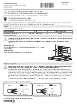
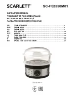
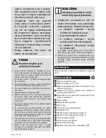
FIGURE 10

CONNECTED UNIT

WATER INLET

POWER CORD

STEAM EXHAUST VENT 
DO NOT CONNECT TO GAS, 
DRAIN OR WATER INLET
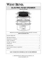
FIGURE 11

CONNECTION-LESS

Summary of Contents for EVOLUTION Series

Page 1: ...installation initial field start up and complete the equipment adjustments described in this manual IMPORTANT WARRANTY INFORMATION WARRANTY REGISTRATION STARTUP FORM INSIDE THIS MANUAL MUST BE REMOVED...

Page 2: ...GENERAL INFORMATION PAGE 5 INSTALLATION PAGE 7 OPERATION USE PAGE 14 OPERATION CLEANING PAGE 18 TROUBLESHOOTING PAGE 21 SERVICE PAGE 22 PREVENTATIVE MAINTENANCE CHECKLIST PAGE 23 WARRANTY PAGE 24 DOC...

Page 3: ...e do not attempt to operate this appliance Improper installation adjustment alteration service or maintenance can cause property damage injury or death Read the installation operating and maintenance...

Page 4: ...ns Name Technicians Email Additional Info 1 Is the steamer being installed at an altitude greater than 2 000 feet Tick Box 2 Is the steamer level Tick Box 3 Is the wall receptacle positioned in a low...

Page 5: ...n less YES NO Type of NEMA Plug Tick One Tick One L6 30P 208 240V 6kW L16 20P 480V 14kW L15 30P 208 240V 10kW IEC 60309 2 230 415V 15 50P 208 240V 15kW 15 Does the Low Water Light and Alarm turn OFF o...

Page 6: ...used here draw attention to activities that may influence safety health protection and the necessity for servicing They help you to prevent problems and the advice will make your work easier WARNING I...

Page 7: ...the base model E Electric B is the size of the unit 6 pan CCC is the supply Voltage D is the number of phases 1 or 3 E is the control series D Manual Fill E Autofill F is the energy input G is the ti...

Page 8: ...ult in performance faults Only professional installation of the device guarantees it high quality operation Check proper setting of the equipment by placing a hotel pan filled with water inside the st...

Page 9: ...ounting hole into the Evolution and tighten securely 4 Once the bottom steamer has been installed carefully lift and place the top Evolution steamer on the horizontal mounting brackets ensuring that t...

Page 10: ...d must be filled throughout the cooking process to assure consistent cook times Do not use the Low Water Indicator as your indication that this steamer requires water as this actually turns off the he...

Page 11: ...pplied with single or 3 phase 3 For use on individual branch circuit only 4 Do not connect to a circuit operating at more than 150V to ground 5 Dimensions outside brackets are inches in brackets are m...

Page 12: ...e steamer If hot is used temperature must be less than 180 F The hose must not be sharply bent kinked or twisted If the steamer is close to a wall use a right angle fitting to prevent kinking the hose...

Page 13: ...ng should have no restrictions and no low spots where water can accumulate Ventilation piping can be directed upwards toward hoods or downward towards floor drains Slightly different approaches are re...

Page 14: ...e steamer vent to a floor drain to allow water condensing in it to run unimpeded into the floor drain 3 For downward sloping extension to a floor drain ONLY ID or larger reinforced silicone hose auto...

Page 15: ...brushes metal scouring pads to clean the cooking chamber bottom 4 1 Operation Introduction The AccuTemp Evolution steamer uses the time proven method of cooking with steam Once the cooking time expire...

Page 16: ...lation Manual I Operation 15 MP4010 1903 OPERATOR DISPLAY COOK or HOLD DISPLAY TEMPERATURE OVER TEMPERATURE LAMP HIGH WATER LAMP LOW WATER LAMP SET TIMER INCREASE VARIABLE DECREASE VARIABLE ON OFF FIG...

Page 17: ...the steamer The display will indicate PrE while in Cook Mode and the temperature while in the Hold Mode 2 Once the steamer is preheated and ready to cook the display will indicate the COO Cook Mode or...

Page 18: ...food into the cooking chamber Shut the door 3 Food will be held at the preset holding temperature The factory default setting is set at 180 F 4 Depress the DISP TEMP button to display the current cook...

Page 19: ...condensate tray with a clean cloth FIGURE 19 Clean the door gasket inside of door and front face of the cooking chamber Clean water sensors with a non metallic cleaning pad Wipe down corners of cooki...

Page 20: ...of the steam collector align the 4 retaining fasteners and hand tighten then install the pan rails and the condensate tray Leave the door open overnight NOTE The steamer will not operate without the...

Page 21: ...activate the chromium oxide passive layer 8 Always rinse the unit with clean water and dry with the steamer door and drain valve open 4 7 5 How to to Protect Stainless Steel All materials used in manu...

Page 22: ...cooking cabinet 5 4 Steamer Does Not Heat If the operators display doesn t light up see Section 5 1 Verify the steamer door is closed as the unit will not heat when the door is open 5 5 Steam Comes Ou...

Page 23: ...ducts Inc Technical Service Department or the service call may not be covered by the limited warranty WARNING Only an AccuTemp Products Inc Authorized Service Personnel or Representative must perform...

Page 24: ...stand casters Monthly Inspect AC power cord for degradation or bare wires Replace if defective or suspect X Inspect door gasket for cuts and degradation Replace if damaged We suggest replacing once a...

Page 25: ...s or workmanship provided the service agency has received advance approval from AccuTemp factory service to perform the repair or replacement This warranty includes travel time not to exceed two hours...

Page 26: ......

Page 27: ...AccuTemp Product Inc Technical Customer Support Technician is available Monday thru Sunday 7 00am to 7 00pm EST 800 480 0415 or 260 469 3040 Phone 800 480 0415 or 260 469 3040 Email service accutemp...

Reviews: