19
ADJUSTMENTS (Continued)
FIG. 25
TO REPLACE THE CARRIAGE LINEAR BEARINGS
7.
Attach the three linear bearing pillow blocks and wiper brack-
ets loosely to the bottom of the carriage, with their tension
adjustment screws (FIG. 23) facing outward.
8. Clean the carriage rails.
NOTE: The two rails are interchangeable and are also
reversible (end-for-end).
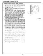
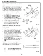
9. Insert a rail through the rear two pillow blocks, and align
the rear pillow blocks to each other with a straight edge
laid along their sides. See FIG. 25. When aligned, tighten
the four socket-head screws which hold each rear pillow
block. Slide the other carriage shaft through the front
bearing, but do not tighten the socket head screws.
10. Lift the complete carriage assembly back onto the
Grinder main base, and secure the rear carriage rail
to its V-groove bosses with the six bolts.
11. With the front rail resting in the V-groove bosses and the
carriage approximately centered on the machine, tighten
the two outside socket-head screws which secure the front
pillow block. Lift the front of the carriage, and tighten the
two inside pillow-block screws. Secure the front carriage
rail to its V-groove bosses with the six bolts.
12. Recheck the bearing tension. The tension is correct when
you try to lift the carriage and can feel no free carriage move-
ment up or down. Check for excessive carriage-traverse
load by using a spring scale to pull on the carriage parallel
to the drive shaft (as in FIG. 19). There should be only about
a 3 lb. pulling force.
To double-check, manually slide the carriage assembly from
one end of its travel to the other. There should be uniform
resistance through the full range of travel.
13. Slide the linear actuator under the carriage, and line up the
hole in the carriage with the tapped hole in the top of the
actuator block. Insert the actuator mounting screw through
the self-aligning bearing, and tighten it. Be careful not to
cross-thread the screw.
14. Reinstall the feed screw guide mounting screws and then the
actuator release lever into the linear actuator.
15. If being used, reattach the two carriage bellows. Refer to
the assembly section of this manual.
Rear Pillow Blocks
Underside of
Carriage
Straightedge
Summary of Contents for 670
Page 36: ...36 ELECTRIC SCHEMATIC 67095233 ...
Page 38: ...38 PARTS LIST 6709534 MAIN BASE ASSEMBLY ...
Page 40: ...40 PARTS LIST Continued 6609529 GRINDING HEAD ASSEMBLY ...
Page 42: ...42 PARTS LIST Continued 6709531 TRAVERSE CARRIAGE ASSEMBLY ...
Page 44: ...44 PARTS LIST Continued 6709533 BEDKNIFE SUPPORT ASSEMBLY ...
Page 46: ...46 PARTS LIST Continued 6709536 CONTROL PANEL ASSEMBLY 50 ...
Page 48: ...48 PARTS LIST Continued 6709536 ELECTRICAL ASSEMBLY ...
Page 50: ...50 PARTS LIST Continued 3708784 COOLANT PUMP TANKASSEMBLY 15 ...
Page 52: ...52 ...


