30
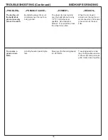
TROUBLESHOOTING (Continued)
ELECTROMAGNETS
--POSSIBLE CAUSE--
--REMEDY--
--REASON--
--PROBLEM--
A--Make certain elecromagnet
switch is on.
B--Verify that Uninteruptable
Power Supply (UPS) is turned
on and that there is 120 VAC at
the ouput.
C--Verify 12 VAC at the input to
the bridge diode.
D--Verify that the 12 Amp fuse
between the transformer and
bridge diode is good.
E--Verify 12 VDC at the output
of the bridge diode.
F--Verify 12 VDC at electro-
magnet switch input.
G--Verify 12 VDC at electro-
magnet switch output.
Electromagnets
do not function.
Switch must be on for
electromagnets to work.
UPS must be turned on and
charged for electromagnet to
work properly.
Power must come thru the
transformer and fuse to the
bridge diode.
Fuse, cord and transformer
must be in working order.
Bridge diode must be in
working order.
Power must get to switch
input.
Power must pass through
the switch and go out to the
electromagnets.
If switch is off, turn on the switch.
With switch on, electromagnets
work, troubleshooting done. With
switch on electromagnets do not
work, Go to B.
If the UPS is off, turn it on.
With UPS on, electromagnets
work, end of troubleshooting.
With UPS on, electromagnets do
not work, check for 120VAC at the
female receptacle at the back of
the UPS. If yes, Go to C. If No,
check continuity of cord #52 from
MAG to UPS. If bad replace cord.
If good, replace or fully charge the
UPS and retest.
Check for 12VAC at termials
71BD2-S and 66BD2-S. If yes, Go
to E. If no, Go to D.
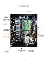
NOTE: With 12 VAC at the bridge
diode input, the light inside the
control box should be ON. If not
replace the bulb.
With a multimeter set to continuity
verify a 0.0 reading when touching
both ends of the fuse. If yes,
check continuity of the cord #51
from the UPS to the transformer. If
good, replace the transformer. If
bad replace the cord. If the fuse
continuity checks bad, replace the
fuse and retry.
Check for 12 VDC at terminals
62BD2-+ and 63DB2--. If yes, Go
to F. If no, replace bridge diode.
Check for 12 VDC at terminals
63EMS-1 and 62EMS-4. If yes,
Go to G. If no, replace wires 62
and 63.
Check for 12 VDC at terminals
58EMS-2 and 59EMS-5. If yes, Go
to H. If no, replace switch.
NOTE: With 12 VDC at electro-
magnet switch terminals 58EMS-2
and 59EMS-5 the light above the
switch on the ouside of the panel
should be ON. If not, replace the
bulb.
Summary of Contents for 670
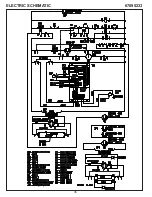
Page 36: ...36 ELECTRIC SCHEMATIC 67095233 ...
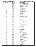
Page 38: ...38 PARTS LIST 6709534 MAIN BASE ASSEMBLY ...
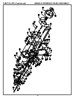
Page 40: ...40 PARTS LIST Continued 6609529 GRINDING HEAD ASSEMBLY ...
Page 42: ...42 PARTS LIST Continued 6709531 TRAVERSE CARRIAGE ASSEMBLY ...
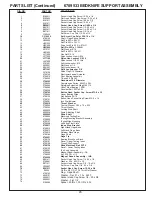
Page 44: ...44 PARTS LIST Continued 6709533 BEDKNIFE SUPPORT ASSEMBLY ...
Page 46: ...46 PARTS LIST Continued 6709536 CONTROL PANEL ASSEMBLY 50 ...
Page 48: ...48 PARTS LIST Continued 6709536 ELECTRICAL ASSEMBLY ...
Page 50: ...50 PARTS LIST Continued 3708784 COOLANT PUMP TANKASSEMBLY 15 ...
Page 52: ...52 ...


