


20
ADJUSTMENT (Continued)
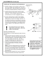
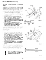
TO ALIGN THE MOTOR SHAFT AND DRIVE
SHAFT
There must be 0.12 to 0.50 in. (3.0 to 12.7 mm) end
clearance between the traverse motor output shaft and
the drive shaft, inside the flexible coupling (FIG.27).
To prevent drive shaft "whipping" at higher traverse
speeds, the two shafts must be aligned so they are
concentric within .010 in. [0.25 mm]. To align:
1. Loosen the two set screw in the coupling.
2. Remove the cover on the outside of the right leg.
3. Loosen the two bolts which secure the motor
assembly to the leg.
4. Visually align the two shafts, then tighten the
motor mounting bolts. Reinstall the leg cover.
5. Check that the spiral gaps in the flexible
coupling are equally spaced, with no compression
or extension load on the coupling, then tighten the
coupling screws.
6. Check that the bearing load block is at 90
o
to the drive shaft (/- 1/4 degree). Use a
precision square held against the bearing
shoulder and the rear rail, as in FIG. 26.
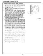
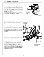
TO ALIGN THE REAR RAIL AND DRIVE SHAFT
The rear carriage rail and the drive shaft must be
precisely aligned:
1. Loosen the two bolts holding the bearing support
blocks at each end of the drive shaft. FIG. 28.
2. Align the drive shaft and rear carriage rail (FIG.
29) so the distance between their facing surfaces
is 3.375"+/- .010 [85.75 mm +/- 0.25]. See FIG.
29.Then tighten the support block bolts.
3. Check that the bearing support blocks are still at
90
o
to the drive shaft (/- 1/4 degree).
Use a precision square held against the bearing
shoulder and the rear rail.
4. If you have difficulty obtaining the above alignment,
check the straightness of the carriage rails (see
below).
NOTE: The vertical and horizontal straightness of the
rails is very accurately set at the factory, so they are
unlikely to be incorrect. Contact the factory if you sus-
pect a problem after making the following tests.
If the drive shaft is adjusted, you
may have to realign the motor shaft
and drive shaft (see above).
Summary of Contents for 670
Page 36: ...36 ELECTRIC SCHEMATIC 67095233 ...
Page 38: ...38 PARTS LIST 6709534 MAIN BASE ASSEMBLY ...
Page 40: ...40 PARTS LIST Continued 6609529 GRINDING HEAD ASSEMBLY ...
Page 42: ...42 PARTS LIST Continued 6709531 TRAVERSE CARRIAGE ASSEMBLY ...
Page 44: ...44 PARTS LIST Continued 6709533 BEDKNIFE SUPPORT ASSEMBLY ...
Page 46: ...46 PARTS LIST Continued 6709536 CONTROL PANEL ASSEMBLY 50 ...
Page 48: ...48 PARTS LIST Continued 6709536 ELECTRICAL ASSEMBLY ...
Page 50: ...50 PARTS LIST Continued 3708784 COOLANT PUMP TANKASSEMBLY 15 ...
Page 52: ...52 ...


