17
TO REPLACE THE LINEAR ACTUATOR BEARINGS
8. Slide the carriage over the actuator, and line up the
hole in the carriage with the tapped hole in the top of
the actuator block. Insert the actuator mounting screw
through the self-adjusting bearing, and tighten the screw.
9. Install the two feed screw guide mounting screws.
Install the actuator release lever into the actuator bar
assembly. Turn the actuator release lever
counterclockwise 1/2 turn to engage the actuator.
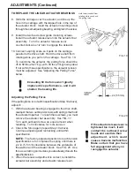
10. Connect a spring scale so it pulls on the carriage
parallel to the drive shaft. Hold the drive shaft from
rotating while you pull on the carriage. See FIG. 19.
To overcome the actuator, the pulling force should be
45 to 60 lbs (20-27 kg), with 50 lbs (23 kg) being ideal.
If not within those specifications, the actuator tension
must be adjusted. See "Adjusting the Pulling Force"
below.
Exceeding 60 lbs force won't greatly
improve drive performance - and it will
shorten the bearing life.
Adjusting the Pulling Force
If the pulling force is not within specification (Step 10 above),
adjust it:
1. With the actuator bearings engaged to the drive shaft,
readjust the two outboard screws with springs that hold
the actuator together. To reach these screws, you must
remove the actuator bar assembly. See FIG. 17.
Turn each outboard screw an equal amount when
resetting. Turn clockwise for more tension.
2. Check the force again (repeat Step 10 above).
Continue adjusting and rechecking until within
specification.
NOTE: The factory-adjusted position to reach tension
specifications is to compress the spring until there is
.22 in. (5.5 mm) clearance between the underside of
the washer and the actuator block. See FIG. 20. Use
this as a starting point unless you are already close to the
specified tension.
3. When the tension adjustment is correct, reinstall the
actuator bar assembly and actuator release lever.
ADJUSTMENTS (Continued)
FIG. 19
FIG. 20
If the actuator release lever is
tightened too much, it will
contact the outboard screw
heads and override their
adjustment, which could
cause a traverse malfunction.
Make certain that you have
full engagement when you
reengage the actuator.
Hold the drive shaft from
rotating while you check
the pulling force.
.22 (5.5mm)
Summary of Contents for 670
Page 36: ...36 ELECTRIC SCHEMATIC 67095233 ...
Page 38: ...38 PARTS LIST 6709534 MAIN BASE ASSEMBLY ...
Page 40: ...40 PARTS LIST Continued 6609529 GRINDING HEAD ASSEMBLY ...
Page 42: ...42 PARTS LIST Continued 6709531 TRAVERSE CARRIAGE ASSEMBLY ...
Page 44: ...44 PARTS LIST Continued 6709533 BEDKNIFE SUPPORT ASSEMBLY ...
Page 46: ...46 PARTS LIST Continued 6709536 CONTROL PANEL ASSEMBLY 50 ...
Page 48: ...48 PARTS LIST Continued 6709536 ELECTRICAL ASSEMBLY ...
Page 50: ...50 PARTS LIST Continued 3708784 COOLANT PUMP TANKASSEMBLY 15 ...
Page 52: ...52 ...


