


12
ASSEMBLY INSTRUCTIONS (Continued)
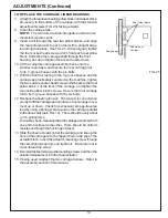
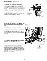
CHECK THE CARRIAGE TRAVERSE
Move the proximity switch assemblies to about 12" [300 mm] from
the ends of the machine, and tighten their knobs.
Visually check that the grinding head will be able to traverse to both
sides of the machine without contacting any
components.
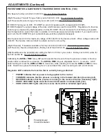
Turn all control panel switches OFF. Set the TRAVERSE FT/MIN
knob to zero. Close the guard door and press START. Press
CARRIAGE TRAVERSE to ON. Set TRAVERSE FT/MIN to a low
speed, and check that the grinding head runs through a complete
traverse cycle. Be prepared to press STOP if there is any
interference. Watch carefully for
obstructions to the head travel, and check that the grinding motor
cord and proximity switch cords are not stretched.
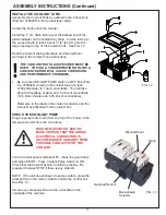
NOTE: If the unit doesn't begin a traverse cycle, press the reset
button on the motor contactor inside the control box. See FIG. 13.
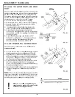
CHECK THE GRINDING MOTOR
Turn all control panel switches OFF. Close the guard door to connect
the interlock. Press START. Press Grinding Motor Switch to ON.
Check that the grinding head runs properly. Be prepared to press
STOP if there is any problem.
NOTE: If the grinding head doesn't begin properly, press the reset
button on the motor contactor inside the control box. See FIG. 13.
MAKE FINAL PREPARATIONS FOR OPERATION
Carefully read the operating instructions in the Operators Manual.
First, study the pages titled "Getting to Know Your Grinder" and
"General Operating Information" for important background
explanations about the machine and about bedknife grinding. Then,
read the "Operating Instructions" pages for step-by-step procedures
on mounting the bedknife and grinding its top and front faces.
Summary of Contents for 670
Page 36: ...36 ELECTRIC SCHEMATIC 67095233 ...
Page 38: ...38 PARTS LIST 6709534 MAIN BASE ASSEMBLY ...
Page 40: ...40 PARTS LIST Continued 6609529 GRINDING HEAD ASSEMBLY ...
Page 42: ...42 PARTS LIST Continued 6709531 TRAVERSE CARRIAGE ASSEMBLY ...
Page 44: ...44 PARTS LIST Continued 6709533 BEDKNIFE SUPPORT ASSEMBLY ...
Page 46: ...46 PARTS LIST Continued 6709536 CONTROL PANEL ASSEMBLY 50 ...
Page 48: ...48 PARTS LIST Continued 6709536 ELECTRICAL ASSEMBLY ...
Page 50: ...50 PARTS LIST Continued 3708784 COOLANT PUMP TANKASSEMBLY 15 ...
Page 52: ...52 ...


