Live view
22
System Settings
Note
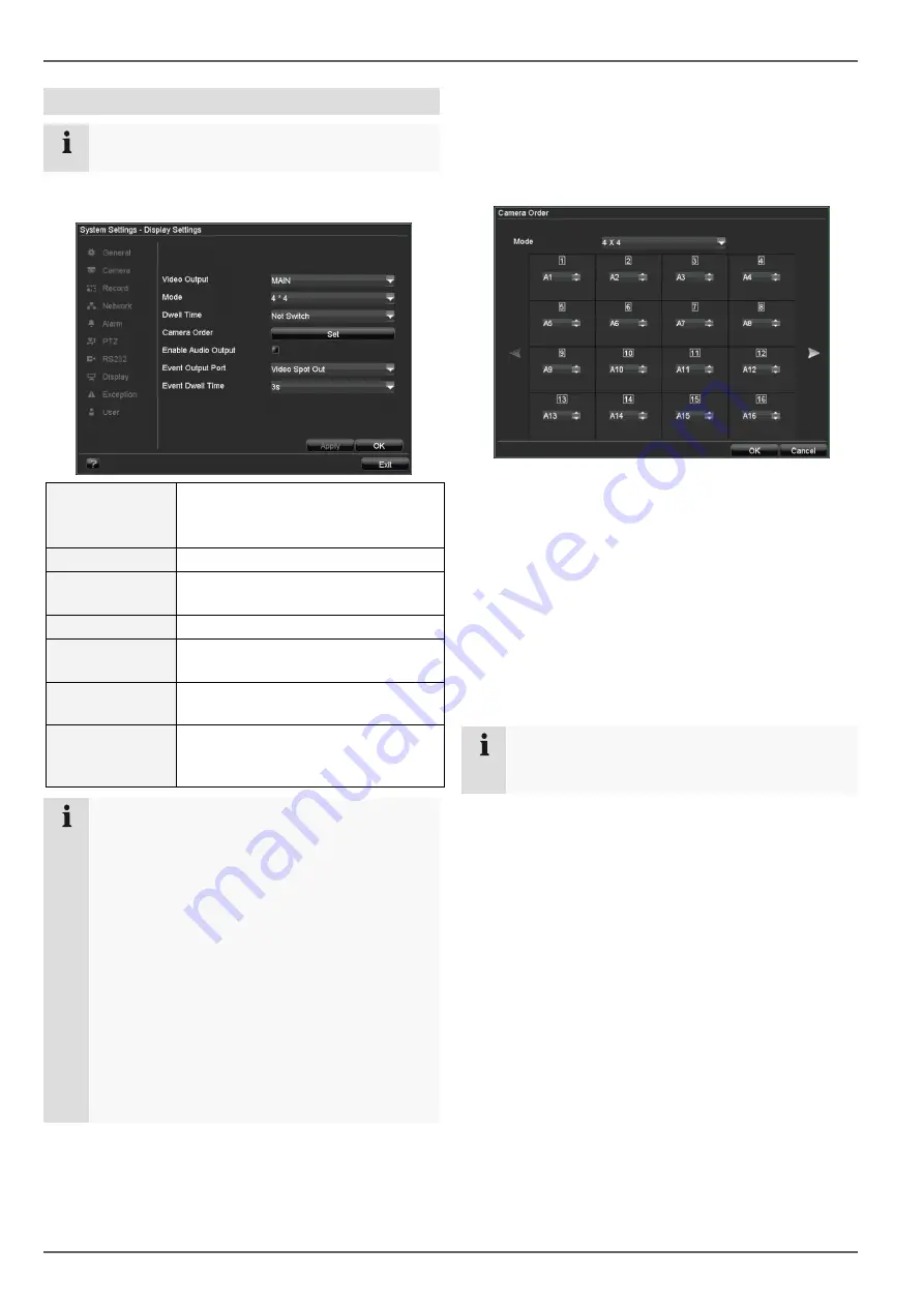
The live view can be set as follows.
Open the main menu, then click on “System Settings”
and then “Display Settings”:
Video Output
VGA, monitor, AUX (CVBS)
Selects the connection where the
settings should be changed
Mode
Various camera layouts
Dwell Time
Switching time between the individ-
ual cameras in “Stop Auto-switch”
Camera Order
Camera order in the live view
Enable Audio
Output
Activates / deactivates audio output
on the video output
Event Output
Port
Used to assign a monitor for event
output
Event Dwell Time The period where the event is dis-
played on the assigned monitor (in
seconds)
Note
VGA monitor connected:
A connected VGA monitor automatically becomes
the main monitor where the audio output is also
assigned. The BNC output Video Spot Out output
displays the cameras in sequence and in full
screen.
If during the boot process of the DVR the VGA cable is not
connected, the main video signal is displayed at BNC output
MAIN. Connect the VGA cable and reboot the DVR in order to
display the main video signal at the VGA output.
No VGA monitor connected:
The main video signal is displayed at BNC output
MAIN. The BNC output Video Spot Out output
displays the cameras in sequence and in full
screen.
Setting the camera output
Up to 16 cameras can be set simultaneously in the live
view.
1. Click on “Set”.
2. Select the display mode.
•
1 x 1
•
2 x 2
•
1 + 5 etc. (the overview changes according to
your settings)
3. The camera signal is assigned to the corresponding
image section using the navigation keys.
•
“X” means that this camera is not displayed.
4. Click on OK to accept the settings.
Note
The output at the spot monitor is always in full
screen.


