background image

Absco Industries

Assembly Instruction Manual

ABSCO SIGNATURE PATIO

MODEL: ADPATIO6030

6.12m W x 3.11m D x  up to 3.18m H

Model: ADPATIO6030

21/09/23

1.0

9  


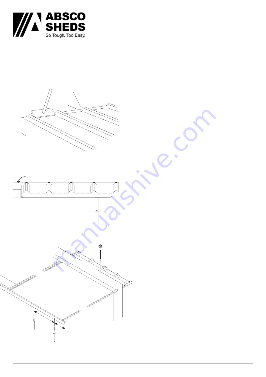
FRONT VIEW - Aligning the first roof panel

Preparing the 

AD1

 panels using a tool before 

inserting into receiver channel.

ROOF PANEL

FLUSH

1

Beam

Beam

Receiver channel

Post

Post

2

FLUSH

UNDERSIDE VIEW

Bottom skin

150

300

3

4

15

o

C

The end with ‘top skin’ overhang & sticker must 

go to the front.

The other end goes into the receiver channel and 

requires some preparation.

A. Check the foam core is flush with the top and 

bottom skins. If it bulges out, safely trim flush with 

a Stanley knife.

B. Check if the steel ‘Bottom skin’ corner is bent 

down below the bottom face. Bend it up with 

pliers.

C. To increase weather protection turn up the 

pans 15 degrees with a turn up/down tool or 

equivalent as shown

Familiarize yourself with the weight and orientation 

of the 

AD1

 panel before lifting.

The ‘bottom skin’ has a protective plastic coating, 

this can be peeled off just before lifting.

Remember to lift and place 

do not slide

, this can 

scratch the panel.

1. 

Safely position the first panel on top of the 

beam and insert into the receiver channel - all the 

way to the right.

The steel ‘top skin’ edge will be flush with right 

end of the receiver channel as shown.

2. 

Check the beam for alignment, the roof panel 

bottom skin is to be flush with the exterior side of 

the beam as shown.

3. 

For now


fix the 

AD1

 panel to the receiver panel 

from below with two 4mm pop rivets 

FAST102.

Inset 150 mm from the right and another 300 mm 

further along.

4. 

Fasten the front edge of the roof panel to 

beam with a tek 14 x 125 mm 

FAST104 

through 

the centre-most rib.

Don’t over-tighten and crush the panel.

For further screw position detail see page 11.

Summary of Contents for ADPATIO6030

Page 1: ...If you are not capable it is recommended you hire a professional NOTE 2 The existing structure should be checked for its capacity to support and tie down this structure prior to construction by a suit...

Page 2: ...the structure must be left for a period of time uncompleted it must be made safe to prevent damage TOOLS REQUIRED Use as a guide other tools equipment may be suitable Safely work within your ability...

Page 3: ...WG 21 1 QTY CHECK 2925 mm 5680 m m 3045 m m 3140 mm 3052 mm 1 QTY CHECK TU 2 QTY CHECK BK3 1 QTY CHECK 2 QTY CHECK 1 QTY CHECK 2 QTY CHECK 2 QTY CHECK 100 QTY CHECK FAST100 200 QTY CHECK FAST101 200 Q...

Page 4: ...hannel is oriented with the longer side to the top A Brickwork Fix 14 x 45mm Tapcon screw every 450mm not suitable for structures with no eaves or two story with blueboard over brick Ensure a minimum...

Page 5: ...rst and it s straight 3 Mark out the anchoring position for the posts next 4 Place the two post bracket BK4 centred over these marks Drill the hole for the anchor using the post baseplate as a templat...

Page 6: ...imum height 3090 mm do not trim post Instead go to step 3 2 Take a post PT5 and mark all faces then safely cut post to length Consider sealing cut with supplied paint 3 Take a BK3 bracket and orientat...

Page 7: ...over the anchored post bracket Make sure the post is orientated so the top bracket is as shown 7 Use a spirit level check the post is vertical and fasten with four FAST100 tek screws and 5 16 nut sett...

Page 8: ...to the top 1 Remove the protective plastic coating from the outside of the beam 2 Safely lift and place a SB2 beam inside the post brackets BK3 as shown Overlap to top Overlap to bottom INTERIOR EXTER...

Page 9: ...he pans 15 degrees with a turn up down tool or equivalent as shown Familiarizeyourselfwiththeweightandorientation of the AD1 panel before lifting The bottom skin has a protective plastic coating this...

Page 10: ...om skin male and female features 6 Carefully push the panel up so it goes all the way into the receiver channel and is flush along the front beam Just like the 1st panel 7 As before fix the panel to t...

Page 11: ...movethetek14x125mmFAST104 from step 4 and insert the other Z flashing TR35 Trim to length so it finishes flush with the edge of the rightmost panel Refit screw through flashing and into original hole...

Page 12: ...kin end is against the top side of the flashing Then continue 30mm down the side 2 Mark off where the Z flashing is against the bottom side of the flashing Then continue 40mm up the side 3 On the side...

Page 13: ...sure the uphill gutter is notched and inside the other 2 Put silicone in the joint and then use two rivets FAST102 per side 3 Take a gutter end stop RWG25 and test fit it over an end of the gutter Ma...

Page 14: ...e rear beam at the point shown 10 Take a string line and make a line from the high to low point 11 Align the bottom of the gutter bracket with the marks and fasten to rear beam using rivets FAST102 Pl...

Page 15: ...tighten and damage Predrilling may be helpful 3 Cut the downpipe to length 4 Place the dropper RWG22 into the top of the downpipe and fasten and seal press into clips and slide up until it touches th...

Page 16: ...s Part 0 General Principles AS NZS 1170 1 2002 Structural Design Actions Part 1 Permanent Imposed Other Actions AS NZS 1170 2 2021 Structural Design Actions Part 2 Wind Actions AS NZS 1170 3 2003 Desi...

Reviews: