


206 / 246
206 / 246
ABOV Semiconductor
AC30M1x64/1x32
PWM Dead-time operation
12.4.6
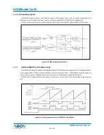
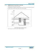
To prevent external short condition, the MPWM provide dead time function. This function is only available for motor
pwm mode. When one of H-side or L-side output changes to active level, amount of dead time will be inserted if
DTEN.MP.DTR bit is enabled.
The duration of dead time is decided a value in DT.MP.DTR[7:0] field.
When DTCLK = 0, the dead time duration = DT[7:0] * (PWM clock period * 4)
When DTCLK = 1, the dead time duration = DT[7:0] * (PWM clock period * 16)
The pwm counter reached at duty value, the pwm output is masked and dead time counter starts to run. When dead
time counter reached the value in DT[7:0] register, the output mask is disabled.
Figure is an example of dead time operation in 1 channel symmetric mode.
Figure 12.7 PWM Dead-time operation timing diagram (Symmetric mode)
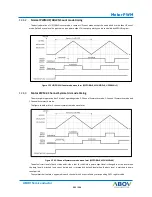
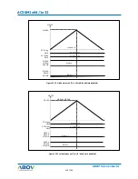
Below figure shows in case of 1-channel asymmetric mode operation.
Figure 12.8 PWM Dead-time operation timing diagram (Asymmetric mode)
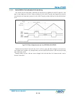
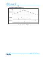
In case of 2-channel symmetric mode, the dead time function is no available. So the dead condition is generated by
each channel duty control.
MP.DUH/V/W
MP0UH
MP0VH
MP0UH
MP0VH
MP.CNT
MP.DTR
MP.DTR
MP.DUL/V/W
MP.DUH/V/W
MP0UH
MP0VH
MP0UH
MP0VH
MP.CNT
MP.DTR
MP.DTR
Summary of Contents for AC30M1x32
Page 3: ...3 246 ABOV Semiconductor INTRODUCTION SECTION 1 INTRODUCTION ...
Page 4: ...4 246 4 246 AC30M1x64 1x32 ABOV Semiconductor OVERVIEW CHAPTER 1 ...
Page 18: ...18 246 18 246 ABOV Semiconductor AC30M1x64 1x32 CPU CHAPTER 2 ...
Page 22: ...22 246 22 246 ABOV Semiconductor AC30M1x64 1x32 Boot Mode CHAPTER 3 ...
Page 26: ...26 246 26 246 ABOV Semiconductor AC30M1x64 1x32 SECTION 2 PERIPHERALS ...
Page 27: ...27 246 ABOV Semiconductor System Control Unit SCU SYSTEM CONTROL UNIT SCU CHAPTER 1 ...
Page 69: ...69 246 ABOV Semiconductor Port Control Unit PCU PORT CONTROL UNIT PCU CHAPTER 2 ...
Page 85: ...85 246 ABOV Semiconductor General Purpose I O GPIO GENERAL PURPOSE I O GPIO CHAPTER 3 ...
Page 92: ...92 246 92 246 AC30M1x64 1x32 ABOV Semiconductor FLASH MEMORY CONTROLLER CHAPTER 4 ...
Page 105: ...105 246 ABOV Semiconductor Internal SRAM INTERNAL SRAM CHAPTER 5 ...
Page 107: ...107 246 ABOV Semiconductor Watch Dog Timer WATCH DOG TIMER WDT CHAPTER 6 ...
Page 113: ...113 246 ABOV Semiconductor 16 bit Timer 16 BIT TIMER CHAPTER 7 ...
Page 129: ...129 246 ABOV Semiconductor FRT FREE RUN TIMER FRT CHAPTER 8 ...
Page 134: ...134 246 134 246 ABOV Semiconductor AC30M1x64 1x32 FUNCTION DESCRIPTION 8 3 ...
Page 135: ...135 246 UART ABOV Semiconductor UNIVERSAL ASYNCHRONOUS CHAPTER 9 RECEIVER TRANSMITTER UART ...
Page 151: ...151 246 ABOV Semiconductor UART Figure 9 6 Transmit interrupt timing diagram ...
Page 152: ...152 246 152 246 ABOV Semiconductor AC30M1x64 1x32 SERIAL PERIPHERAL INTERFACE SPI CHAPTER 10 ...
Page 164: ...164 246 164 246 ABOV Semiconductor AC30M1x64 1x32 I2 C Interface CHAPTER 11 ...
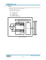
Page 185: ...185 246 ABOV Semiconductor Motor PWM MOTOR PULSE WIDTH MODULATOR CHAPTER 12 MPWM ...
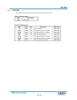
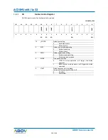
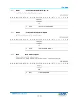
Page 215: ...215 246 ABOV Semiconductor Divider DIVIDER DIV64 CHAPTER 13 ...
Page 221: ...221 246 ABOV Semiconductor 12 BIT A D Converter 12BIT A D CONVERTER CHAPTER 14 ...
Page 235: ...235 246 ABOV Semiconductor CHARACTERISTIC SECTION 3 CHARACTERISTIC ...
Page 236: ...236 246 236 246 ABOV Semiconductor AC30M1x64 1x32 Electrical Characteristic CHAPTER 1 ...
Page 243: ...243 246 ABOV Semiconductor Package Package CHAPTER 2 ...