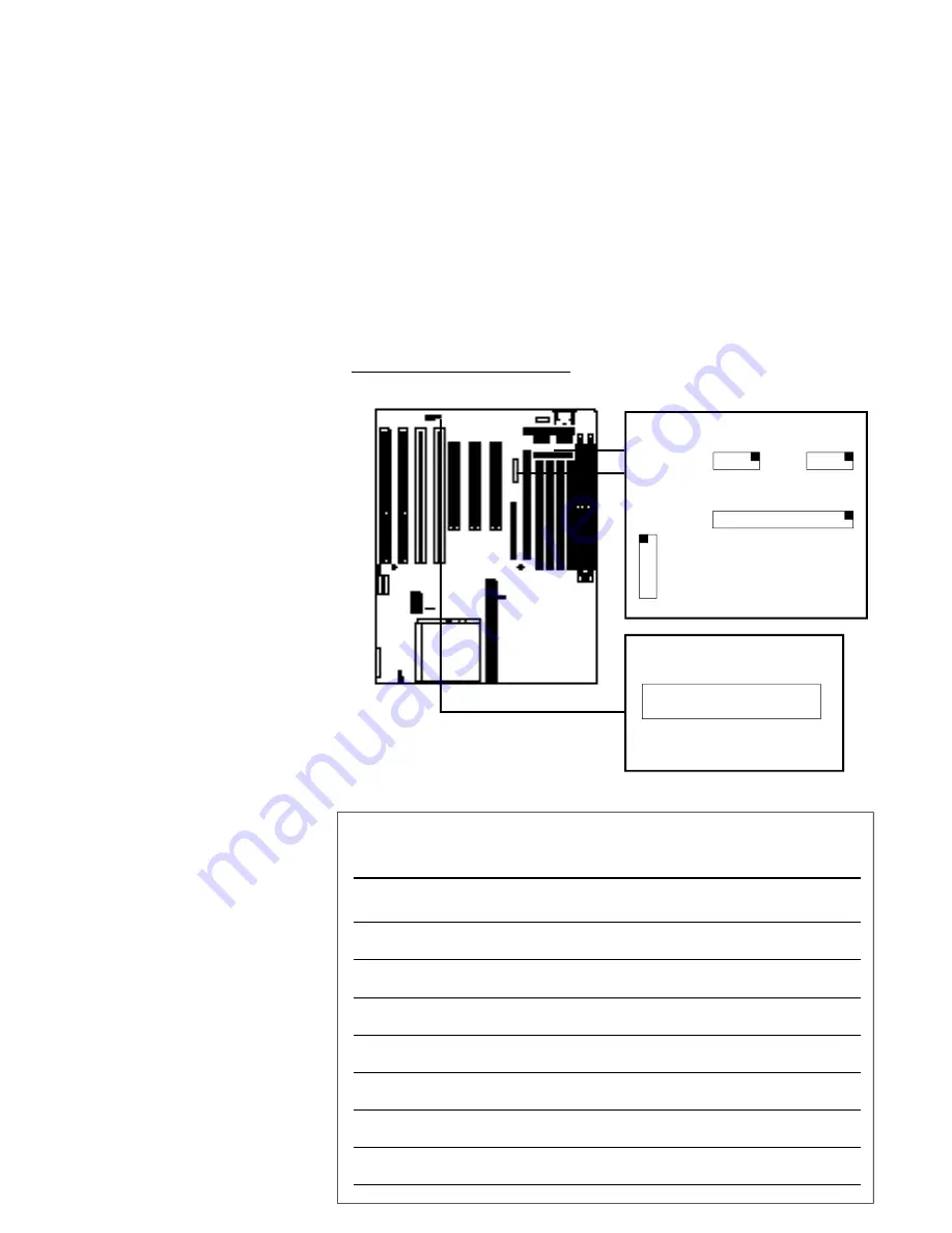
I/O Port Connectors
The PR5 has two serial, one parallel, a connector for an
IrDA-compatible Infrared port and a dual-port USB con-
nector onboard. Combination ribbon cable to external
port cables are supplied for each connector except the
Infrared port. W hen installing ports, make sure the col-
ored edge of the ribbon cable is at the Pin 1 end of the
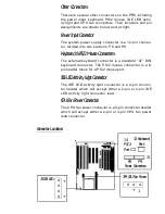
onboard connector. Their positions and Pin 1 locations
are shown below and the pin assignments for the Infra-
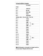
red and USB ports are shown in the table on page 2-11.
I/O Port Connectors
There are five connectors:
JP2: Infrared port (5-pin)
USB: USB ports (16-pin)
COM1: COM1 serial port (10-pin)
COM2: COM2 serial port (10-pin)
LPT: LPT1 printer port (26-pin)
Pin 1
: Upper left-hand corner for
USB, upper right-hand corner for
COM & LPT as shown at right.
U S B
C O M 1
C O M 2
LPT
I/O Port Connector Locations
x x x x x
JP2 IR Connector
Pin 1
Connector Summary
N a m e
# Pins
Function
I D E 1
4 0
IDE Channel 1 connector
IDE2
4 0
IDE Channel 2 connector
F D C
3 4
Floppy Disk connector
LPT
2 6
Parallel Port connector
C O M 1
1 0
Serial Port COM1 connector
C O M 2
1 0
Serial Port COM2 connector
U S B
1 6
Universal Serial Bus connector
Summary of Contents for PR5
Page 10: ...System Block Diagram ...


