BIOS Setup
3-27
3-11. Set Password
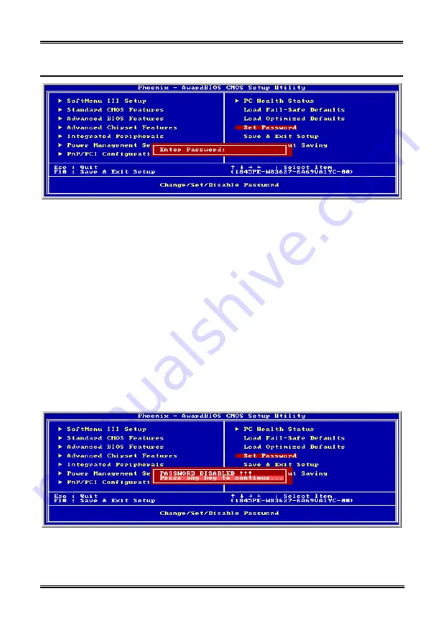
Figure 3-14. Set Password Screen Shot
Set Password:
You can enter but do not have the right to change the options of the setup menus. When
you select this function, the following message will appear at the center of the screen to
assist you in creating a password.
ENTER PASSWORD:
Type the password, up to eight characters in length, and press <Enter>. The password typed now will
clear any previously entered password from CMOS memory. You will be asked to confirm the password.
Type the password again and press <Enter>. You may also press <Esc> to abort the selection and not
enter a password.
To disable a password, just press <Enter> when you are prompted to enter the password. A message will
confirm the password will be disabled. Once the password is disabled, the system will boot and you can
enter Setup freely.
PASSWORD DISABLED.
When a password has been enabled, you will be prompted to enter it every time you try to enter Setup.
This prevents an unauthorized person from changing any part of your system configuration.
Additionally, when a password is enabled, you can also require the BIOS to request a password every
time your system is rebooted. This would prevent unauthorized use of your computer.
Figure 3-15. Password Disabled Screen Shot
You can determine when the password is required within the BIOS Features Setup Menu and its Security
option. If the Security option is set to “System”, the password will be required both at boot and at entry to
Setup. If it is set to “Setup”, the prompting only occurs when trying to enter Setup.
User’s Manual
Summary of Contents for BE7-G
Page 19: ...Introduction 1 3 1 2 Layout Diagram BE7 G User s Manual...
Page 20: ...1 4 Chapter 1 1 3 Layout Diagram BE7 S BE7 Series...
Page 21: ...Introduction 1 5 1 4 Layout Diagram BE7 RAID User s Manual...
Page 22: ...1 6 Chapter 1 1 5 Layout Diagram BE7 B BE7 Series...
Page 23: ...Introduction 1 7 1 6 Layout Diagram BE7 User s Manual...
Page 24: ...1 8 Chapter 1 1 8 Chapter 1 BE7 Series BE7 Series...
Page 39: ...Hardware Setup 2 15 13 IDE1 IDE2 and IDE3 IDE4 Connectors User s Manual...
Page 72: ...A 2 Appendix A A 2 Appendix A BE7 Series BE7 Series...
Page 84: ...E 2 Appendix E BE7 Series...
Page 86: ...F 2 Appendix F F 2 Appendix F BE7 Series BE7 Series...
Page 112: ...L 6 Appendix L Thank You ABIT Computer Corporation http www abit com tw BE7 Series...


