BIOS Setup
3-9
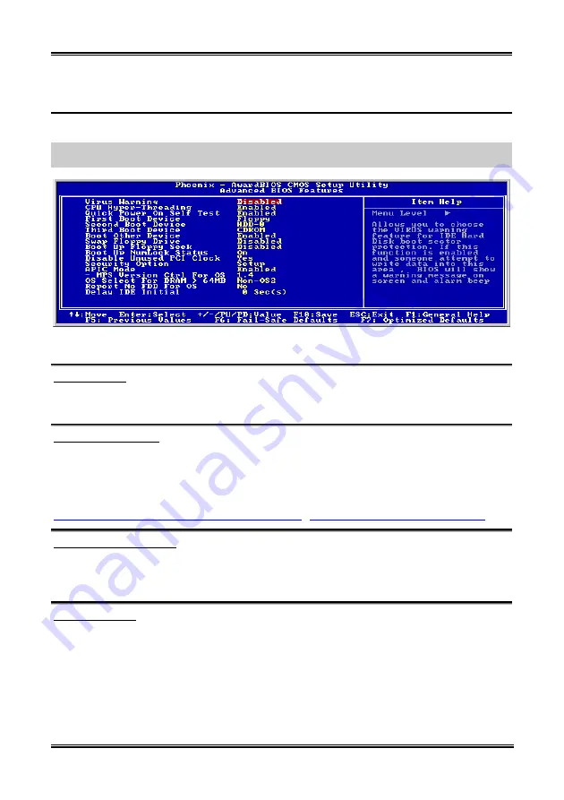
3-3. Advanced BIOS Features Setup Menu
With each item, you can press <Enter> at any time to display all the options for that item.
ATTENTION:
Advanced BIOS Features Setup Menu has already been set for maximum operation. If
you do not really understand each of the options in this menu, we recommend you use the default values.
Figure 3-5. Advanced BIOS Features Setup Screen
Virus Warning:
When this feature is enabled, if there is any attempt from a software or an application to access the boot
sector or the partition table, the BIOS will warn you that a boot virus is attempting to access the hard disk.
CPU Hyper-Threading
Leave this item to its default setting to enable the simultaneous multi-threaded (SMT) processor so as to
make one physical processor looks like two logical processors to the OS and applications.
This option is for CPU with Hyper-Threading Technology only. For more information on
“Hyper-Threading Technology”, please visit Intel Web site at
http://www.intel.com/homepage/land/hyperthreading.htm
http://www.intel.com/design/chipsets/ht/
.
Quick Power On Self Test:
After the computer has been powered on, the BIOS of the motherboard will run a series of tests in order
to check the system and its peripherals. If the Quick Power on Self-Test feature is enabled, the BIOS will
simplify the test procedures in order to speed up the boot process. The default setting is
Enabled
.
First Boot Device:
When the computer boots up, the BIOS attempts to load the operating system from the devices in the
sequence selected in these items: floppy disk drive A, LS/ZIP devices, hard drive C, SCSI hard disk drive
or CD-ROM. There are eleven options for the boot sequence that you can choose (The default setting is
Floppy
.):
Floppy
LS120
HDD-0
SCSI
CDROM
HDD-1
HDD-2
HDD-3
ZIP100
LAN
ATA133RAID
Disabled.
User’s Manual
Summary of Contents for BE7-G
Page 19: ...Introduction 1 3 1 2 Layout Diagram BE7 G User s Manual...
Page 20: ...1 4 Chapter 1 1 3 Layout Diagram BE7 S BE7 Series...
Page 21: ...Introduction 1 5 1 4 Layout Diagram BE7 RAID User s Manual...
Page 22: ...1 6 Chapter 1 1 5 Layout Diagram BE7 B BE7 Series...
Page 23: ...Introduction 1 7 1 6 Layout Diagram BE7 User s Manual...
Page 24: ...1 8 Chapter 1 1 8 Chapter 1 BE7 Series BE7 Series...
Page 39: ...Hardware Setup 2 15 13 IDE1 IDE2 and IDE3 IDE4 Connectors User s Manual...
Page 72: ...A 2 Appendix A A 2 Appendix A BE7 Series BE7 Series...
Page 84: ...E 2 Appendix E BE7 Series...
Page 86: ...F 2 Appendix F F 2 Appendix F BE7 Series BE7 Series...
Page 112: ...L 6 Appendix L Thank You ABIT Computer Corporation http www abit com tw BE7 Series...


