


26
User’s guide VUBB
|
1ZSC000562-AAL en
9
9 9 9 9 8 7
LOWER
POSITION
RAISE
9
8
7
6
5
4
10 11
12
13
14
–
+
9
8
7
6
5
4
10 11
12
13
14
–
+
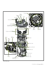
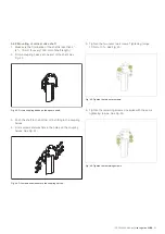
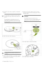
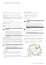
Fig. 58. BUE: Red mark on the brake disc.
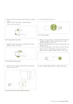
Fig. 57. BUL2: Cam disc and roller on the brake arm.
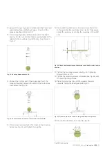
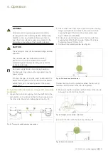
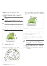
To access the position indicator, remove the cover.
See Fig. 60.
22. If the motor-drive mechanism is out of position, manually
crank the motor-drive mechanism to the exact position
according to the
info
box above.
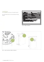
Fig. 60. Position indicator on the tap-changer.
23. Check that the position indicators on the motor-drive
mechanism (Fig. 59) and the tap-changer (Fig. 60) show
the same position.
WARNING
If the position indicators on the motor-drive
mechanism and on the tap-changer do
not
show the
same position, a serious transformer failure could
occur.
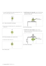
Fig. 59. Position indicator on the motor-drive mechanism.
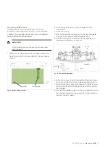
21. Check that the motor-drive mechanism is at the EXACT
position.
The exact position for the BUL is when the roller on
the brake arm is in the notch of the cam disc. See
Fig. 57.
The exact position for the BUE is when the red
indicator flag is in position and the red mark on the
brake disc is aligned with the red mark on the brake
pad. See Fig. 58.


