1ZSC000562-AAL en
|
User’s guide VUBB
21
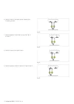
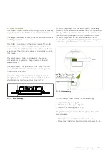
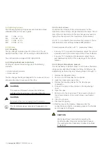
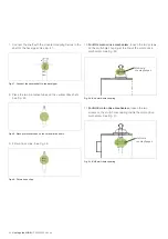
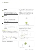
Fig. 34. Tighten the two outer screws.
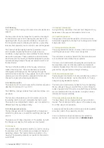
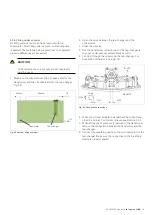
Fig. 35. Tighten the remaining screws.
4. Push the shaft to the bottom of the fitting in the coupling
halves.
5. Tighten the two outer screws. Tightening torque
10 Nm ±10 %. See Fig. 34.
6. Tighten the remaining screws crosswise with the same
tightening torque. See Fig. 35.
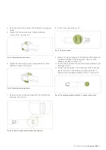
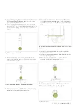
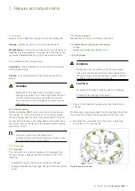
7. Position the two protective tubes with the slotted ends
outwards. See Fig. 36.
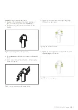
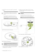
8. Fit two hose clips. See Fig. 37.
9. Apply a thin layer of grease to all spherical shaft ends and
unpainted surfaces of the bevel gears. Use any of the
greases specified in Section 3.3.
10. Connect the shaft with the mounted coupling halves to the
bevel gear shaft.
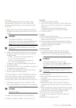
11. Fit two coupling halves on the other end of the shaft; see
Fig. 32. Be sure to offset these coupling halves 90° in
relation to the couplings mounted in step 2. See Fig. 38.
Fig. 36. Position the tubes with the slotted ends outwards.
Fig. 37. Fit two hose clips.
Fig. 38. The couplings should be offset 90° in relation to each other.

