


1ZSC000562-AAL en
|
User’s guide VUBB
35
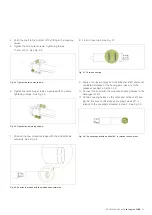
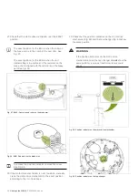
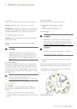
Fig. 70. Hose clips on the protective tube.
13. Push the protective tube aside.
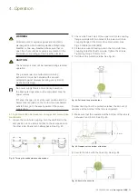
14. Remove the bevel gear. See Fig. 71.
Be sure not to twist the horizontal drive shaft.
Fig. 71. Bevel gear.
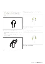
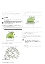
15. Refit the bevel gear on the tap-changer cover.
Once the bevel gear is back in place, it is important to
check that the vertical drive shaft has not been disturbed.
Synchronize the shaft as described in section 4.1.
16. Check that the position indicator in the motor-drive
mechanism (Fig. 59) shows the same position as the
indicator inside the top-cover of the tap-changer (Fig. 60).
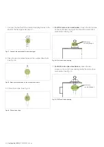
WARNING
If the position indicators on the motor-drive
mechanism and on the tap-changer do
not
show the
same position, a serious transformer failure could
occur.
To access the position indicator, remove the cover.
17. Refit the protective tube with the greater diameter
upwards, facing the bevel gear. See Fig. 55.
18. Secure the hose clip on the protective tube facing the
bevel gear. See Fig. 56.
7.3 Replacement of pressure relay
If the pressure relay fails to pass the insulation test and/or
the function test, it must be replaced. This is described in the
assortment guide.
CAUTION
It is not permitted to only replace the microswitch
inside the pressure relay.
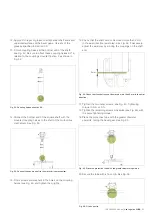
O-ring
Bevel gear flange
Clamps
Tap-changer cover
Fig. 72. Refit the bevel gear box cover.


