


14
User’s guide VUBB
|
1ZSC000562-AAL en
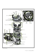
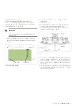
2.3.3 Housing
The purpose of the housing is to seal and provide mechanical
support.
The top section forms the flange that is used for mounting to
the transformer cover, and for bearing the gear box for the
operating shafts. The top section includes a connection for
the conservator pipe and draining connections, a grounding
terminal, the supervisory device and the cover with its gasket.
The housing has high quality seals that guarantee vacuum
and overpressure-proof performance under all service
conditions. During operation, some particles from mechanical
wear will be produced. These pollutants must not enter the
transformer, and the housing is therefore designed to provide
hermetical sealing between the vacuum selector switch and
the transformer.
The top and bottom sections of the housing cylinder are
made of cast aluminum. They are attached to a cylinder
of fiberglass-reinforced plastic. The bushings through the
cylinder wall are sealed by O-ring gaskets. Each unit is tested
under vacuum, and the outside is exposed to helium and
checked for leaks with a helium gas detector.
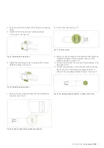
2.3.4 Selector switch
The selector switch is used to execute the electrical sequence
described in Sections 2.2.1 and 2.2.2.
The VUBB tap-changer contains three selector switches, one
per phase.
The function of the selector switch is to select a tap in the
tap winding and to carry and commutate the load current.
The selector has multiple fixed contacts, each connected to a
different tap in the regulating winding.
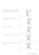
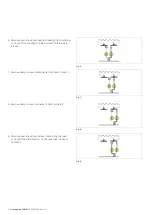
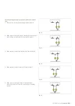
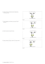
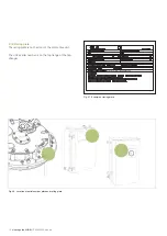
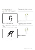
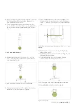
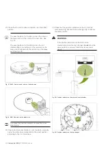
2.3.5 Change-over selector
The tap-changer can also be equipped with a change-over
selector for plus/minus or coarse/fine switching; see Figs. 22
and 23.
The selector switch has a maximum of 10 positions, but with
the change-over selector, this number can be doubled.
2.4 Contacts
The contacts inside the selector switch are used for carrying
the electrical load. The contacts are comprised of fixed and
operating contacts. The fixed contacts are located on the
housing. The operating contacts are located on the selector
switch shaft.
2.5 Vacuum interrupters
During switching operations of vacuum tap-changers, arcing
takes place in the vacuum interrupters and not in oil.
2.6 Transition resistors
The purpose of the transition resistors is to allow a make-
before-break operation by limiting the circulating current when
bridging two taps.
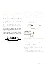
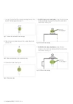
2.7 Spring-loaded mechanism
The spring-loaded mechanism ensures a fast and complete
switching sequence even if the power supply fails.
The mechanism is normally operated by the motor-drive unit,
but can also be hand-cranked by an operator.
The motor-drive mechanism and bevel gear are mounted on
the transformer tank, and the drive shafts are mounted to
complete the assembly of the motor-drive mechanism, bevel
gear and tap-changer before oil filling and testing.
2.8 Motor-drive mechanism
The bevel gear, mounted on the cover, transfers the motion of
the motor-drive mechanism, via the drive shafts, to the tap-
changer’s spring-loaded mechanism.
The motor-drive mechanism provides the force for operating
the tap-changer. Energy is provided from a motor through a
series of gears and out through a drive shaft. Several features
are incorporated within the mechanism to lengthen service
intervals and improve reliability.
2.9 Accessories and protection devices
The tap-changer can be equipped with various protection
devices. The standard protection device is the pressure relay.
An oil flow relay is also available.
A pressure relief device with an alarm signal is also available,
as well as certain other supervisory sensors.
For more information about accessories and protection
devices, see the technical description.
1ZSC000562-AAD
.


