IB 6.2.7.7-3I
5
If the Retaining Strap is not removed, the
UVTD
will not be able to trip the breaker.
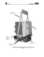
If it is necessary to raise or move the breaker,
attach a lifting yoke to the truck or a fifth wheel to
transport the breaker as required. See Figure A1
in the Appendix.
General Inspection
Inspect the condition of the circuit breaker vacuum
interrupters and electrical connections prior to
installing the circuit breaker into the compartment.
Even though each circuit breaker is completely
adjusted and tested at the factory, shipping and
handling conditions, and/or incorrect storage could
cause defects.
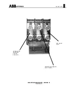
The front cover and barrier assembly (Figure A3
or A4) must be removed for access to and
inspection of the vacuum interrupters and their
associated adjustments.
Vacuum Interrupter Examination
WARNING
If the circuit breaker has been energized, or it is
unsure if the circuit breaker has ever been
energized, the mid-band ring (on vacuum
interrupters so equipped) must first be discharged
before any work is performed on or near the
interrupters. A grounding stick must be used to
discharge the ring by fastening the ground cable of
the stick to a known ground and touching the
grounding tip of the stick to each mid-band ring.
The insulated vacuum container should be
examined carefully for cracks in the area of the
metal-to-insulation interface seals on both ends
and around the Mid-Band Ring. Since a certain
amount of transmitted light is usually required to
detect cracks, the inspection should be done in a
well lighted area. If the mid-band ring, when so
equipped, has been bent by accidental impact,
that area should be specially scrutinized for seal
damage. Small external chips will not impair the
useful life of the interrupter.
Barrier and Insulation Inspection
All barriers and insulated parts should be checked
for damage. Any dust or dirt should be removed
by compressed air or with a clean lint-free cloth. If
these parts have become contaminated with any
heavy dirt or grease, a clean, lintless cloth
saturated with alcohol should be used.
The lead support moldings are polyester glass and
occasionally have some resin rich cracks or
crazing that develops. These do not indicate
defective material and should not cause concern.
Installing Front Barrier
Install the assembly and fasten with four lower
front barrier screws and one screw on each side,
inside the front barrier.
Note: It is recommended that a dielectric
withstand test be performed prior to initially putting
this or any type vacuum circuit breaker into
service. Refer to "Dielectric Tests" in the
"Adjustments, Tests and Periodic Maintenance"
section for the correct test procedure.
Manual Operation For Inspection
The electrically operated circuit breakers can be
charged manually with a removable Manual
Charge Handle for bench tests or emergency
operation. The removable Manual Charge Handle
is an accessory and is supplied only when
ordered.
Position the handle onto the Manual Charging
Lever
hooked section in the long slot on the Pawl
Carrier (See Figure A5 in the Appendix).
The
small tabs on the Manual Charging Handle will fit
in the small holes of the Pawl Carrier. Push down
on the Manual Charging Handle until it will not
travel any further. This partially charges the
Closing Springs. Repeat this operation until the
charging mechanism is heard to snap over center
(approximately 10 operations), and the Spring
Indicator clearly shows the message SPRINGS
CHARGED. The circuit breaker can now be
closed by pulling out on the Manual Close Lever.
The Circuit Breaker can then be closed by
pressing the Manual Trip Button. See Figures A3
and A4 in the Appendix.


