IB 6.2.7.7-3
6
Padlock Hasp Provision
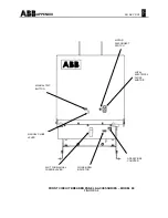
Refer to Figure A6 located in the Appendix. The
Racking Mechanism Padlock Hasp provision
permits the breaker to be padlocked in the
DISCONNECT and TEST positions. This
provision is accomplished by the Padlock Hasp
blocking the Blocking Lever attached to the
Racking Release Assembly, preventing the Rack
Screw from being rotated clockwise to the
release
position. If not functioning properly, the Adjustable
Link must be adjusted as follows.
1. Remove the lower Front Panel of the
breaker.
2. Remove the Retaining Ring from one of
the pins securing the Adjustable Link.
3. Rotate the free end of the Adjustable Link
to vary its length, so that when
reconnected to the pin, the padlock
functions as noted above.
4. Replace the Retainer.
5. This adjustment might effect feature "D" of
the "Interlocks (
Racking Mechanism
)",
below, and it should be checked also.
NOTE: As a special option, the breaker may be
ordered with Three-Position Padlocking, which
also permits the breaker to be padlocked in the
CONNECT position.
Interlocks
(Racking Mechanism)
The four mechanical interlocks that work in
conjunction with the Racking Mechanism to
protect both user and breaker should function as
specified below. If malfunction is identified and
the recommended adjustments do not correct the
problems consult the factory before placing the
breaker in service.
Refer to the next sections "Installing Circuit
Breaker Into Compartment" and "Removing Circuit
Breaker" for a complete description of the Racking
Mechanism components and operation.
A. When in the WITHDRAW position, the
Closing Springs will discharge automatically.
If the Closing Springs have been previously
charged, they will discharge when the racking
mechanism reaches this position. This is
accomplished by a linkage, activated by an
Adjusting Screw on a welded tab at the center
of the Rack Shaft. This pulls the Discharge
Link Assembly which releases the Close Latch
to its unlatched position. If the interlock does
not function as specified, adjust as follows:
1. Make sure Racking Mechanism is in the
DISCONNECT position.
2. Following the instructions in "Removal
from DISCONNECT Position," rotate the
Rack Screw counterclockwise. The
Manual Close Lever should begin moving
after one-half (1/2) turn from the
DISCONNECT position.
3. If the Manual Close Lever requires more
than one-half (1/2) turn to begin moving,
then adjustment of the Adjusting Screw on
the Racking Shaft will have to be made.
The gap between the Adjusting Screw and
the Discharge Link Assembly is between
0.010” – 0.031”. See Figure A7 in the
Appendix.
B. The Rack Screw cannot be turned to move the
breaker starting from the DISCONNECT,
TEST and CONNECT positions, unless the
Release Lever is first operated. A finger in the
Index Lever engages one of three holes in the
Rack Screw corresponding to each of the
previously mentioned positions, preventing it
from rotating. Turning the Release Lever to
the left disengages the finger from the hole,
allowing the Rack Screw to be rotated.
1. If the Rack Screw can be rotated without
turning the Release Lever, check if the
Release Lever is jammed in the left
(
release
) position. If so, see if it can be
freed.
2. Visually inspect that the finger of the Index
Lever is engaging in the corresponding
hole in the Rack Screw.


