IB 6.2.7.7-3
1
2
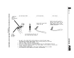
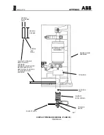
Gap and Contact Wipe are inversely related;
increasing one decreases the other, and visa-
versa. Also, note that no more than one-half (1/2)
turn should be required when readjusting for
contact sequence.
After completing the contact sequence procedure,
recheck the Contact Wipe and gap for each pole.
If the specified Contact Gap, Contact Wipe and
contact sequencing cannot all be obtained, and it
is determined that the breaker is operating
properly, the interrupter is in need of replacement.
The front cover and interphase barrier assembly
can now be reinstalled. Return the rack screw to
its original position by turning it counterclockwise
approximately two to three turns until it stops.
Closing and Opening Times
After the operation intervals, it is recommended
that the Closing and Cpening Times be checked.
This can be done by use of a cycle counter, travel
recorder or oscillograph to monitor the time from
coil energizing to contact kiss (closing) or part
(opening).
Note: Normally, the Closing Time is not critical.
The breaker performance is satisfactory if the
Closing Speed, Opening Speed and Opening
Time are within specification. See Table A3 in the
Appendix for the nominal values for these
parameters.
The circuit breaker closing and opening times
should be within the time ranges for normal
operation.
Note the following:
•
Times are from signal initiation to primary
contact kiss (make) or break.
•
Times for DC controls supplied by a rectified
unconditioned power source, and all AC
controls, may wander by as much as ±4ms
due to the "current-zeroes" associated with
such currents.
•
Below 0°C, the closing times will increase
(but with no reduction in closing force), and
opening times will usually be within the
limits.
•
Adjustments to correct times, if found to be
outside limits, are critical and the nearest
District Office should be contacted for
recommendations.
Closing and Opening Speeds
The Closing and Opening speeds of the Primary
Contacts can be determined by use of a travel
recorder, which records their linear travel versus
time. The output can be fed into a travel recorder
or oscilloscope.
Before the Closing and Opening speeds are
checked, the Contact Wipe should first be
inspected. This is because, in addition to the
energy provided by The Opening Springs, the
Contact Springs provide additional acceleration
energy through the wipe distance upon contact
part. As the Primary Contacts erode, the Contact
Wipe decreases, and the opening speed will
decrease. Speed should still be within
acceptable limits if the wipe is still within limits.
Refer to Table A3 in the Appendix.
WARNING
Do not attempt to increase the opening speed by
readjusting the push rod to gain more contact wipe.
If either of the speeds is too slow, and the Contact
Wipe is within the limits specified, examine the
breaker for any moving parts that appear to be
binding. If none can be found, consult the factory
for assistance.
Operating Mechanism
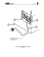
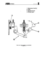
Trip Latch Engagement (Bite) (See Figure
A10).
The Latch Engagement Adjusting Screw (3) is
located
at the right of the right-hand mechanism
housing (1). It can be reached easily from the top
of the breaker, after removal of the top cover
plate.
To adjust the Latch (2) Engagement, proceed as
follows:


