


PRIM AR Y TESTING
VOLTAGE SENSOR S
1VLG5000 17 C
33
4.3.3
Voltage sensor installed on busbars
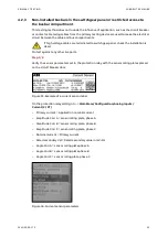
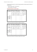
Step 1/8
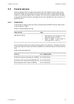
Verify sensor parameters set in the protection relay with the sensor rating plates placed on
the circuit breaker door.
Figure 45: Example of a voltage sensor label
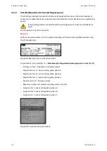
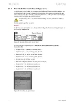
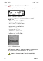
On the protection relay LHMI go to ->
Main Menu/Configuration/Analog inputs/Voltage (3U,
VT)
–
Primary voltage = nominal voltage of the network
–
VT connection = Wye (star connection)
–
Amplitude Corr A = sensor rating plate, phase A
–
Amplitude Corr B = sensor rating plate, phase B
–
Amplitude Corr C = sensor rating plate, phase C
–
Division ration = 10 000
–
Voltage input type = CVD sensor
–
Angle Corr A = sensor rating plate, phase A
–
Angle Corr B = sensor rating plate, phase B
–
Angle Corr C = sensor rating plate, phase C
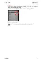
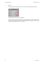
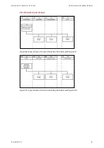
Figure 46: Voltage sensor parameters
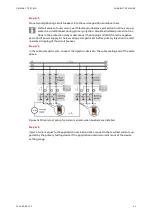
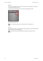
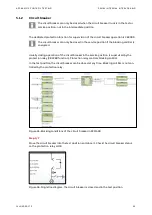
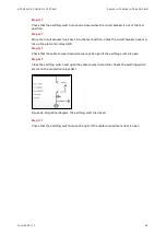
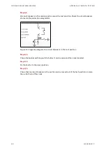
Step 2/8
Isolate the whole bus section. All circuit breakers belong to the relative busbar section move
into the test position.
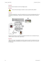
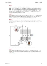
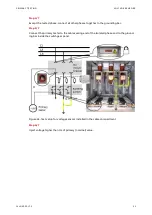
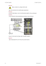
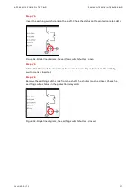
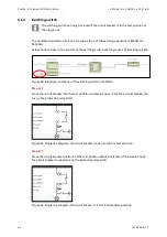
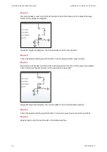
Step 3/8
Select one outgoing switchgear panel in the section to apply voltage on the main bus. Re-
move the circuit breaker out of the switchgear panel and close the earthing switch
Summary of Contents for UniGear Digital
Page 1: ...DISTRIBUTION SOLUTIONS UniGear Family UniGear Digital Commissioning and testing Guide...
Page 2: ......
Page 3: ...DISTRIBUTION SOLUTIONS UniGear Family UniGear Digital Commissioning and testing Guide...
Page 6: ......
Page 10: ......
Page 12: ......
Page 96: ......
Page 98: ...Visit us www abb com mediumvoltage Document Number 1VLG500017 Rev C...