


CURRENT S ENSORS
PRIM AR Y TESTING
26
1VLG5000 17 C
4.2.4
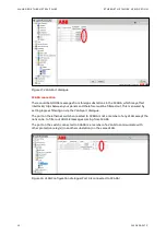
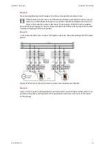
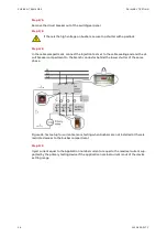
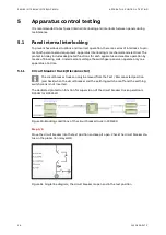
Non-installed busbars in the switchgear panel
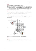
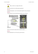
This testing method includes the influence of application, such as the circuit breaker or con-
tactor, which are used to make an electrical circuit between the cable and busbar compart-
ments. The abovementioned testing method is preferred by switchgear factories for the pri-
mary testing of current sensors in a workshop.
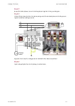
If high voltage cables are terminated to switchgear panel, check the installation is
dead.
Protect against any other live parts.
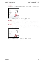
Step 1/7
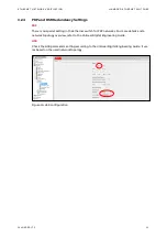
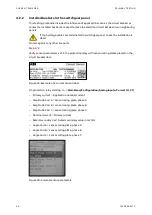
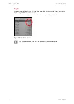
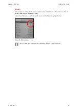
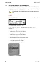
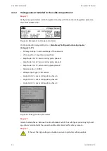
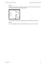
Verify the sensor parameters set in the protection relay with the sensor rating plates placed
on the circuit breaker door.
Figure 37: Example of a current sensor label
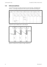
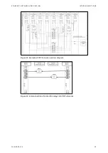
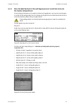
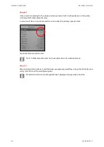
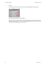
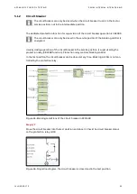
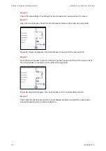
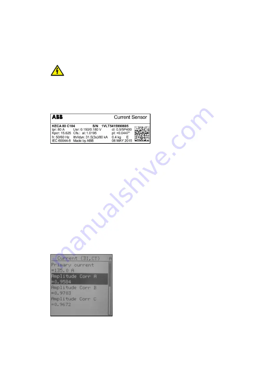
On the protection relay LHMI go to ->
Main Menu/Configuration/Analog inputs/
Current (3I, CT)
–
Primary current = Application nominal current
–
Amplitude Corr A = sensor rating plate, phase A
–
Amplitude Corr B = sensor rating plate, phase B
–
Amplitude Corr C = sensor rating plate, phase C
–
Nominal current = Primary current
–
Rated secondary Val = Rated secondary value in mV/Hz
–
Angle Corr A = sensor rating plate, phase A
–
Angle Corr B = sensor rating plate, phase B
–
Angle Corr C = sensor rating plate, phase C
Figure 38: Current sensor parameters
Summary of Contents for UniGear Digital
Page 1: ...DISTRIBUTION SOLUTIONS UniGear Family UniGear Digital Commissioning and testing Guide...
Page 2: ......
Page 3: ...DISTRIBUTION SOLUTIONS UniGear Family UniGear Digital Commissioning and testing Guide...
Page 6: ......
Page 10: ......
Page 12: ......
Page 96: ......
Page 98: ...Visit us www abb com mediumvoltage Document Number 1VLG500017 Rev C...