


—
94-1100-00002874 A0
USER MANUAL
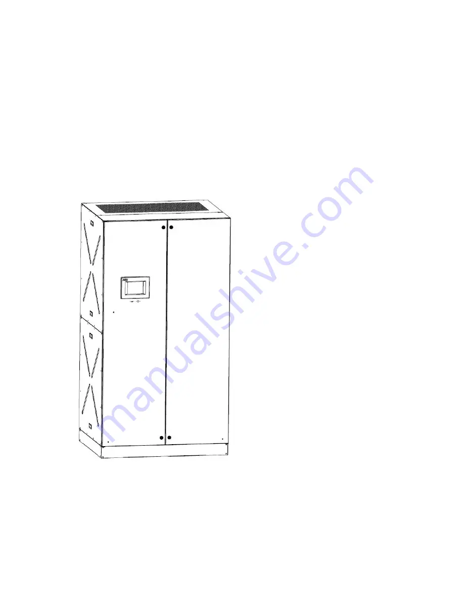
TruFit™
Power Distribution Unit
50-300 kVA
The ABB TruFit
™
PDU offers the most
reliable and flexible power distribution
product on the market today with
almost unlimited configurations of
panelboards and sub-feed breakers to
meet every load requirement. One
cabinet design supports ratings up to
300kVA.
For a comprehensive overview of
publications available for the ABB
TruFit™ PDU product line, refer to the
inside cover of this publication. Web
link and QR code references are also
included.


