background image

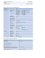
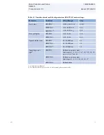
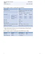
Table 29. Directional earth-fault protection (DEFxPDEF)

Characteristic

Value

Operation accuracy


Depending on the frequency of the current
measured: f

n

 ±2 Hz

DEFLPDEF

Current:
±1.5% of the set value or ±0.002 x I

n

Voltage
±1.5% of the set value or ±0.002 x U

n

Phase angle:
±2°

DEFHPDEF

1)

Current:
±1.5% of the set value or ±0.002 x I

n

(at currents in the range of 0.1…10 x I

n

)

±5.0% of the set value
(at currents in the range of 10…40 x I

n

)

Voltage:
±1.5% of the set value or ±0.002 x U

n

Phase angle:
±2°

Start time 

2)3)


Minimum

Typical

Maximum

DEFHPDEF

1)

I

Fault

 = 2 x set 

Start

value

 
42 ms

 
44 ms

 
46 ms

DEFLPDEF
I

Fault

 = 2 x set 

Start

value

61ms

64 ms

66 ms

Reset time

< 40 ms

Reset ratio

Typical 0.96

Retardation time

< 30 ms

Operate time accuracy in definite time mode

±1.0% of the set value or ±20 ms

Operate time accuracy in inverse time mode

±5.0% of the theoretical value or ±20 ms 

4)

Suppression of harmonics

RMS: No suppression
DFT: -50 dB at f = n x f

n

, where n = 2, 3, 4, 5,


Peak-to-Peak: No suppression

1) Not included in REM615
2) Set 

Operate delay time

 = 0.06 s,

Operate curve type

 = IEC definite time, 

Measurement mode

 = default (depends on

stage), current before fault = 0.0 x I

n

, f

n

 = 50 Hz, earth-fault current with nominal frequency injected from

random phase angle, results based on statistical distribution of 1000 measurements

3) Includes the delay of the signal output contact
4) Maximum 

Start value

 = 2.5 x I

n

Start value

 multiples in range of 1.5 to 20

Motor Protection and Control

1MRS756890 D

REM615
Product version: 3.0

Issued: 2010-06-29

32

ABB

Summary of Contents for RELION REM615

Page 1: ...Relion 615 series Motor Protection and Control REM615 Product Guide ...

Page 2: ...lection and ordering data 54 24 Accessories and ordering data 58 25 Tools 59 26 Terminal diagrams 61 27 References 65 28 Functions codes and symbols 65 29 Document revision history 68 Disclaimer The information in this document is subject to change without notice and should not be construed as a commitment by ABB Oy ABB Oy assumes no responsibility for any errors that may appear in this document C...

Page 3: ...IEC 60870 5 103 Modbus and DNP3 2 Standard configuration REM615 is available in three alternative standard configurations The standard signal configuration can be altered by means of the graphical signal matrix or the optional graphical application functionality of the Protection and Control IED Manager PCM600 Further the application configuration functionality of the IED supports the creation of ...

Page 4: ...tection instance 1 Frequency protection instance 1 Frequency protection instance 2 Negative sequence overcurrent protection for motors instance 1 Negative sequence overcurrent protection for motors instance 2 Loss of load supervision Motor load jam protection Motor start up supervision Phase reversal protection Thermal overload protection for motors Circuit breaker failure protection Master trip i...

Page 5: ...rent measurement instance 1 Three phase voltage measurement Residual voltage measurement Sequence voltage measurement Three phase power and energy measurement including power factor RTD mA measurement o o Frequency measurement included o optional at the time of order 1 Note that all directional protection functions can also be used in non directional mode 2 The instances of a protection function r...

Page 6: ...ion Further the B and C configurations offer frequency protection including overfrequency underfrequency and rate of change frequency protection modes The RTD mA module offered as an option for standard configurations A and B enable the use of the optional multipurpose protection function which can be used for tripping and alarm purposes using RTD mA measuring data or analog values via GOOSE messa...

Page 7: ...ID B0430A61 AAA8 424B AB30 5D5D6A0375FE V1 EN Figure 1 Protection function overview of standard configuration A Motor Protection and Control 1MRS756890 D REM615 Product version 3 0 Issued 2010 06 29 ABB 7 ...

Page 8: ...ID 3CDDC6F1 6747 4CC8 9D6F 72C3895A496B V1 EN Figure 2 Protection function overview of standard configuration B Motor Protection and Control 1MRS756890 D REM615 Product version 3 0 Issued 2010 06 29 8 ABB ...

Page 9: ...e current transformers in Holmgreen summation connection can also be used for earth fault protection In that case possible unwanted operations of the earth fault protection at motor start up due to CT saturation can be prevented using the IED s internal interlocking features or a suitable stabilizing resistor in the common neutral return The optional RTD mA module offered for standard configuratio...

Page 10: ...values can if required be sent to other IEDs using analog horizontal GOOSE messaging Temperature values can also vice versa be received from other IEDs over the station bus thus increasing the extent of relevant information Motor Protection and Control 1MRS756890 D REM615 Product version 3 0 Issued 2010 06 29 10 ABB ...

Page 11: ...motor start up signal from each REM615 is connected to the Restartinhibit inputs of the other REM615s Hence while one motor is starting up the starting of the other motors is inhibited The same motor start up signal is also used to dynamically increase the setting level of the lowest O C protection stage of the REF615 on the incoming feeder The optional RTD mA inputs are utilized for motor winding...

Page 12: ...tion level COM600 uses the data content of the bay level IEDs to offer enhanced substation level functionality COM600 features a web browser based HMI providing a customizable graphical display for visualizing single line mimic diagrams for switchgear bay solutions The SLD feature is especially useful when 615 series IEDs without the optional single line diagram feature are used Further the web HM...

Page 13: ...erential communication Binary signal transfer OPC COM600 Web HMI COM600 Web HMI COM600 Ethernet switch ABB System 800xA Analog and binary horizontal GOOSE communication IEC 61850 Analog and binary horizontal GOOSE communication IEC 61850 GUID 6984D893 45D5 427A BABF F1E1015C18E2 V2 EN Figure 5 Industrial power system example using 615 series IEDs Station Automation COM600 and System 800xA Motor Pr...

Page 14: ...rbance recorder The IED is provided with a disturbance recorder featuring up to 12 analog and 64 binary signal channels The analog channels can be set to record either the waveform or the trend of the currents and voltage measured The analog channels can be set to trigger the recording function when the measured value falls below or exceeds the set values The binary signal channels can be set to s...

Page 15: ...ny hours the motor has been in operation thus enabling scheduling of time based preventive maintenance of the motor 12 Trip circuit supervision The trip circuit supervision continuously monitors the availability and operability of the trip circuit It provides open circuit monitoring both when the circuit breaker is in its closed and in its open position It also detects loss of circuit breaker cont...

Page 16: ... allow connection of either 1 A or 5 A secondary current transformers The optional residual current input 0 2 1 A is normally used in applications requiring sensitive earth fault protection and featuring core balance current transformers The three phase voltage inputs and the residual voltage input covers the rated voltages 60 210 V Both phase to phase voltages and phase to earth voltages can be c...

Page 17: ...e IEC 61850 8 1 GOOSE Generic Object Oriented Substation Event profile Binary GOOSE messaging can for example be employed for protection and interlocking based protection schemes The IED meets the GOOSE performance requirements for tripping applications in distribution substations as defined by the IEC 61850 standard Further the IED supports the sending and receiving of analog values using GOOSE m...

Page 18: ...me stamped events changing the active setting group and uploading of the latest fault records If a Modbus TCP connection is used five clients can be connected to the IED simultaneously Further Modbus serial and Modbus TCP can be used in parallel and if required both IEC 61850 and Modbus protocols can be run simultaneously The IEC 60870 5 103 implementation supports two parallel serial bus connecti...

Page 19: ...V1 EN Figure 6 Self healing Ethernet ring solution Table 5 Supported station communication interfaces and protocols Interfaces Protocols Ethernet Serial 100BASE TX RJ 45 100BASE FX LC RS 232 RS 485 Fibre optic ST IEC 61850 MODBUS RTU ASCII MODBUS TCP IP DNP3 serial DNP3 TCP IP IEC 60870 5 103 Supported Motor Protection and Control 1MRS756890 D REM615 Product version 3 0 Issued 2010 06 29 ABB 19 ...

Page 20: ...of Un 38 264 V AC 50 120 of Un 12 72 V DC 80 120 of Un 38 4 300 V DC Start up threshold 19 2 V DC 24 V DC 80 Burden of auxiliary voltage supply under quiescent Pq operating condition DC 12 0 W nominal 18 0 W max AC 16 0 W nominal 21 0W max DC 12 0 W nominal 18 0 W max Ripple in the DC auxiliary voltage Max 15 of the DC value at frequency of 100 Hz Maximum interruption time in the auxiliary DC volt...

Page 21: ...0 210 V AC Voltage withstand Continuous 2 x Un 240 V AC For 10 s 3 x Un 360 V AC Burden at rated voltage 0 05 VA 1 Ordering option for residual current input 2 Residual current and or phase current Table 9 Binary inputs Description Value Operating range 20 of the rated voltage Rated voltage 24 250 V DC Current drain 1 6 1 9 mA Power consumption 31 0 570 0 mW Threshold voltage 18 176 V DC Reaction ...

Page 22: ...ensing current Maximum 0 33 mA rms Operation accuracy Resistance Temperature 2 0 or 1 Ω 1 C 10 Ω copper 2 C mA inputs Supported current range 0 20 mA Current input impedance 44 Ω 0 1 Operation accuracy Resistance 0 5 or 0 01 mA Table 11 Signal outputs and IRF output Description Value Rated voltage 250 V AC DC Continuous contact carry 5 A Make and carry for 3 0 s 10 A Make and carry 0 5 s 15 A Brea...

Page 23: ...sion circuit 1 5 mA Minimum voltage over the TCS contact 20 V AC DC 15 20 V Table 13 Single pole power output relays Description Value Rated voltage 250 V AC DC Continuous contact carry 5 A Make and carry for 3 0 s 15 A Make and carry for 0 5 s 30 A Breaking capacity when the control circuit time constant L R 40 ms at 48 110 220 V DC 1 A 0 25 A 0 15 A Minimum contact load 100 mA at 24 V AC DC Tabl...

Page 24: ... min Modulation Unmodulated Logic level TTL Level Current consumption 2 4 mA Power consumption 10 20 mW 1 According to 200 04 IRIG standard Table 17 Lens sensor and optical fibre for arc protection Description Value Fibre optic cable including lens 1 5 m 3 0 m or 5 0 m Normal service temperature range of the lens 40 100 C Maximum service temperature range of the lens max 1 h 140 C Minimum permissi...

Page 25: ...s with an LC communication interface the maximum operating temperature is 70 ºC Table 20 Environmental tests Description Type test value Reference Dry heat test humidity 50 96 h at 55ºC 16 h at 85ºC1 IEC 60068 2 2 Dry cold test 96 h at 25ºC 16 h at 40ºC IEC 60068 2 1 Damp heat test cyclic 6 cycles 12 h 12 h at 25 C 55 C humidity 93 IEC 60068 2 30 Storage test 96 h at 40ºC 96 h at 85ºC IEC 60068 2 ...

Page 26: ... IEC 60255 22 6 class III IEC 61000 4 6 10 V m rms f 80 2700 MHz IEC 61000 4 3 IEC 60255 22 3 class III 10 V m f 900 MHz ENV 50204 IEC 60255 22 3 class III 20 V m rms f 80 1000 MHz IEEE C37 90 2 2004 Fast transient disturbance tests IEC 61000 4 4 IEC 60255 22 4 IEEE C37 90 1 2002 All ports 4kV Surge immunity test IEC 61000 4 5 IEC 60255 22 5 Communication 1 kV line to earth Other ports 4 kV line t...

Page 27: ...ary inputs only 300 V rms 150 V rms IEC 61000 4 16 IEC 60255 22 7 class A Emission tests EN 55011 class A IEC 60255 25 Conducted 0 15 0 50 MHz 79 dB µV quasi peak 66 dB µV average 0 5 30 MHz 73 dB µV quasi peak 60 dB µV average Radiated 30 230 MHz 40 dB µV m quasi peak measured at 10 m distance 230 1000 MHz 47 dB µV m quasi peak measured at 10 m distance Motor Protection and Control 1MRS756890 D R...

Page 28: ...esistance 100 MΏ 500 V DC Protective bonding resistance IEC 60255 27 Resistance 0 1 Ώ 4 A 60 s Table 23 Mechanical tests Description Reference Requirement Vibration tests sinusoidal IEC 60068 2 6 test Fc IEC 60255 21 1 Class 2 Shock and bump test IEC 60068 2 27 test Ea shock IEC 60068 2 29 test Eb bump IEC 60255 21 2 Class 2 Seismic test IEC 60255 21 3 Class 2 Table 24 Product safety Description R...

Page 29: ...rence EMC directive 2004 108 EC Standard EN 50263 2000 EN 60255 26 2007 Table 26 RoHS compliance Description Complies with RoHS directive 2002 95 EC Motor Protection and Control 1MRS756890 D REM615 Product version 3 0 Issued 2010 06 29 ABB 29 ...

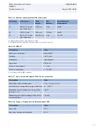
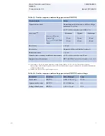
Page 30: ...ardation time 30 ms Operate time accuracy in definite time mode 1 0 of the set value or 20 ms Operate time accuracy in inverse time mode 5 0 of the theoretical value or 20 ms 4 Suppression of harmonics RMS No suppression DFT 50 dB at f n x fn where n 2 3 4 5 Peak to Peak No suppression P to P backup No suppression 1 Not included in REM615 2 Set Operate delay time 0 02 s Operate curve type IEC defi...

Page 31: ...Operate delay time PHLPTOC 40 200000 ms 10 PHHPTOC1 40 200000 ms 10 PHIPTOC 20 200000 ms 10 Operating curve type2 PHLPTOC Definite or inverse time Curve type 1 2 3 4 5 6 7 8 9 10 11 12 13 14 15 17 18 19 PHHPTOC1 Definite or inverse time Curve type 1 3 5 9 10 12 15 17 PHIPTOC Definite time 1 Not included in REM615 2 For further reference please refer to the Operating characteristics table Motor Pro...

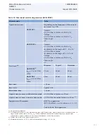
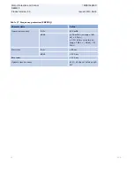
Page 32: ... ratio Typical 0 96 Retardation time 30 ms Operate time accuracy in definite time mode 1 0 of the set value or 20 ms Operate time accuracy in inverse time mode 5 0 of the theoretical value or 20 ms 4 Suppression of harmonics RMS No suppression DFT 50 dB at f n x fn where n 2 3 4 5 Peak to Peak No suppression 1 Not included in REM615 2 Set Operate delay time 0 06 s Operate curve type IEC definite t...

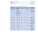
Page 33: ...rate delay time DEFLPDEF 60 200000 ms 10 DEFHPDEF1 40 200000 ms 10 Operating curve type2 DEFLPDEF Definite or inverse time Curve type 1 2 3 4 5 6 7 8 9 10 11 12 13 14 15 17 18 19 DEFHPDEF1 Definite or inverse time Curve type 1 3 5 15 17 Operation mode DEFLPDEF and DEFHPDEF1 1 Phase angle 2 IoSin 3 IoCos 4 Phase angle 80 5 Phase angle 88 1 Not included in REM615 2 For further reference refer to the...

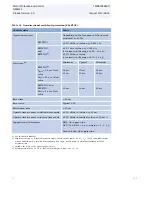
Page 34: ...t ratio Typical 0 96 Retardation time 30 ms Operate time accuracy in definite time mode 1 0 of the set value or 20 ms Operate time accuracy in inverse time mode 5 0 of the theoretical value or 20 ms 4 Suppression of harmonics RMS No suppression DFT 50 dB at f n x fn where n 2 3 4 5 Peak to Peak No suppression 1 Not included in REM615 2 Measurement mode default depends on stage current before fault...

Page 35: ...te delay time EFLPTOC 40 200000 ms 10 EFHPTOC 40 200000 ms 10 EFIPTOC1 20 200000 ms 10 Operating curve type2 EFLPTOC Definite or inverse time Curve type 1 2 3 4 5 6 7 8 9 10 11 12 13 14 15 17 18 19 EFHPTOC Definite or inverse time Curve type 1 3 5 9 10 12 15 17 EFIPTOC1 Definite time 1 Not included in REM615 2 For further reference please refer to the Operating characteristics table Motor Protecti...

Page 36: ...1 0 x Un Voltage before fault 1 1 x Un fn 50 Hz undervoltage in one phase to phase with nominal frequency injected from random phase angle results based on statistical distribution of 1000 measurements 2 Includes the delay of the signal output contact 3 Minimum Start value 0 50 Start value multiples in range of 0 90 to 0 20 Table 34 Three phase undervoltage protection PHPTUV main settings Paramete...

Page 37: ...or 20 ms Suppression of harmonics DFT 50 dB at f n x fn where n 2 3 4 5 1 Start value 1 0 x Un Positive sequence voltage before fault 1 1 x Un fn 50 Hz positive sequence undervoltage with nominal frequency injected from random phase angle results based on statistical distribution of 1000 measurements 2 Includes the delay of the signal output contact Table 36 Positive sequence undervoltage protecti...

Page 38: ...z df dt 100 mHz s in range df dt 5 Hz s 2 0 of the set value in range 5 Hz s df dt 15 Hz s Start time f f 80 ms df dt 120 ms Reset time 150 ms Operate time accuracy 1 0 of the set value or 30 ms Motor Protection and Control 1MRS756890 D REM615 Product version 3 0 Issued 2010 06 29 38 ABB ...

Page 39: ...0 1 200 xFn 0 001 1 050 Frequency start value overfrequency Start value Freq 0 800 1 100 xFn 0 001 0 950 Frequency start value underfrequency Start value df dt 0 200 0 200 xFn s 0 005 0 010 Frequency start value rate of change Operate Tm Freq 80 200000 ms 10 200 Operate delay time for frequency Operate Tm df dt 120 200000 ms 10 400 Operate delay time for frequency rate of change Motor Protection a...

Page 40: ... 0 of the set value or 20 ms Suppression of harmonics DFT 50 dB at f n fn where n 2 3 4 5 1 Negative sequence voltage before fault 0 0 Un fn 50 Hz negative sequence overvoltage with nominal frequency injected from random phase angle results based on statistical distribution of 1000 measurements 2 Includes the delay of the signal output contact Table 40 Negative sequence overvoltage protection NSPT...

Page 41: ...3 Suppression of harmonics DFT 50 dB at f n x fn where n 2 3 4 5 1 Negative sequence current before 0 0 fn 50 Hz results based on statistical distribution of 1000 measurements 2 Includes the delay of the signal output contact 3 Start value multiples in range of 1 10 to 5 00 Table 42 Negative phase sequence overcurrent protection for motors MNSPTOC main settings Parameter Function Value Range Step ...

Page 42: ...ameter Function Value Range Step Start value high LOFLPTUC 0 01 1 00 x In 0 01 Start value low LOFLPTUC 0 01 0 50 x In 0 01 Operate delay time LOFLPTUC 400 600000 ms 10 Operation LOFLPTUC Off On Table 45 Motor load jam protection JAMPTOC Characteristic Value Operation accuracy Depending on the frequency of the current measured fn 2 Hz 1 5 of the set value or 0 002 x In Reset time 40 ms Reset ratio...

Page 43: ...perate time accuracy 1 0 of the set value or 20 ms Reset ratio Typical 0 90 1 Current before 0 0 x In fn 50 Hz overcurrent in one phase results based on statistical distribution of 1000 measurements 2 Includes the delay of the signal output contact Table 48 Motor start up supervision STTPMSU main settings Parameter Function Value Range Step Motor start up A STTPMSU 1 0 10 0 x In 0 1 Motor start up...

Page 44: ...ution of 1000 measurements 2 Includes the delay of the signal output contact Table 50 Phase reversal protection PREVPTOC main settings Parameter Function Value Range Step Start value PREVPTOC 0 05 1 00 x In 0 01 Operate delay time PREVPTOC 100 60000 ms 10 Operation PREVPTOC Off On Table 51 Three phase thermal overload protection for motors MPTTR Characteristic Value Operation accuracy Depending on...

Page 45: ...actor MPTTR 1 00 1 20 0 01 Weighting factor p MPTTR 20 0 100 0 0 1 Time constant normal MPTTR 80 4000 s 1 Time constant start MPTTR 80 4000 s 1 Operation MPTTR Off On Table 53 Circuit breaker failure protection CCBRBRF Characteristic Value Operation accuracy Depending on the frequency of the current measured fn 2 Hz 1 5 of the set value or 0 002 x In Operate time accuracy 1 0 of the set value or 2...

Page 46: ...60000 ms 10 CB fault delay CCBRBRF 0 60000 ms 10 Table 55 Arc protection ARCSARC Characteristic Value Operation accuracy 3 of the set value or 0 01 x In Operate time Minimum Typical Maximum Operation mode Light current 1 2 9 ms 12 ms 15 ms Operation mode Light only 2 9 ms 10 ms 12 ms Reset time 40 ms Reset ratio Typical 0 96 1 Phase start value 1 0 x In current before fault 2 0 x set Phase start v...

Page 47: ...ristic Value Operation accuracy 1 0 of the set value or 20 ms Table 58 Multipurpose analog protection MAPGAPC main settings Parameter Function Value Range Step Start value MAPGAPC 10000 0 10000 0 0 1 Operate delay time MAPGAPC 0 200000 ms 100 Operation mode MAPGAPC Over Under Control functions Table 59 Emergency startup ESMGAPC main settings Parameter Function Value Range Step Operation ESMGAPC Of...

Page 48: ... accuracy Depending on the frequency of the current measured f fn 2 Hz 0 5 or 0 002 x In at currents in the range of 0 01 4 00 x In Suppression of harmonics DFT 50 dB at f n x fn where n 2 3 4 5 RMS No suppression Table 62 Three phase voltage measurement VMMXU Characteristic Value Operation accuracy Depending on the frequency of the voltage measured fn 2 Hz At voltages in range 0 01 1 15 x Un 0 5 ...

Page 49: ... range 0 01 1 15 x Un 1 0 or 0 002 x Un Suppression of harmonics DFT 50 dB at f n x fn where n 2 3 4 5 Table 65 Three phase power and energy PEMMXU Characteristic Value Operation accuracy At all three currents in range 0 10 1 20 x In At all three voltages in range 0 50 1 15 x Un At the frequency fn 1 Hz Active power and energy in range PF 0 71 Reactive power and energy in range PF 0 71 1 5 for pow...

Page 50: ...asurement 25 Ω per lead Isolation 2 kV inputs to protective earth Response time 4 s RTD resistance sensing current Maximum 0 33 mA rms Operation accuracy Resistance Temperature 2 0 or 1 Ω 1 C 10 Ω copper 2 C mA inputs Supported current range 0 20 mA Current input impedance 44 Ω 0 1 Operation accuracy Resistance 0 5 or 0 01 mA Table 67 Frequency measurement FMMXU Characteristic Value Operation accu...

Page 51: ...alue Operate time1 NPS function UFault 1 1 x set Neg Seq voltage Lev 33 ms UFault 5 0 x set Neg Seq voltage Lev 18 ms Delta function ΔU 1 1 x set Voltage change rate 30 ms ΔU 2 0 x set Voltage change rate 24 ms 1 Includes the delay of the signal output contact fn 50 Hz fault voltage with nominal frequency injected from random phase angle results based on statistical distribution of 1000 measuremen...

Page 52: ... using the web browser based user interface The default SLD can be modified according to user requirements by using the graphical display editor in PCM600 The local HMI includes a push button L R for local remote operation of the IED When the IED is in the local mode the IED can be operated only by using the local front panel user interface When the IED is in the remote mode the IED can execute co...

Page 53: ...o IEDs Alternatively the IED can be mounted in 19 instrument cabinets by means of 4U Combiflex equipment frames For the routine testing purposes the IED cases can be equipped with test switches type RTXP 18 which can be mounted side by side with the IED cases Mounting methods Flush mounting Semi flush mounting Semi flush mounting in a 25 tilt Rack mounting Wall mounting Mounting to a 19 equipment ...

Page 54: ...r part of the plug in unit An order number label is placed on the side of the plug in unit as well as inside the case The order number consists of a string of codes generated from the IED s hardware and software modules Use the ordering key information to generate the order number when ordering complete IEDs H B M B C CAH B C C 1 B B N 1 X D DESCRIPTION 1 IED 615 series IED including case H 615 se...

Page 55: ...1 A 12 BI 10 BO AADAD Std conf A 4I Io 1 5 A 6 RTD 2 mA 4 BI 6 BO AAGAB Std conf A 4I Io 0 2 1 A 6 RTD 2 mA 4 BI 6 BO AAHAB Std conf B 4I Io 1 5 A 3U 8 BI 10 BO BCAAH Std conf B 4I Io 1 5 A 3U 14 BI 13 BO BCAAJ Std conf B 4I Io 0 2 1 A 3U 8 BI 10 BO BCBAH Std conf B 4I Io 0 2 1 A 3U 14 BI 13 BO BCBAJ Std conf B 4I Io 1 5 A 3U 6 RTD 2 mA 8 BI 10 BO BCCAH Std conf B 4I Io 0 2 1 A 3U 6 RTD 2 mA 8 BI ...

Page 56: ...x RJ 45 Serial RS 485 connector RS 232 485 D Sub 9 connector input for IRIG B cannot be combined with arc protection BB 3 x RJ 45 BD and FX 2 x RJ 45 1 x LC BC Ethernet 100Base FX 1 x LC NA Ethernet 100Base TX 1 x RJ 45 NB Ethernet 100Base TX 2 x RJ 45 1 x LC NC Ethernet 100Base TX 3 x RJ 45 ND No communication module NN If serial communication is chosen please choose a serial communication module...

Page 57: ...BEE D8C0233BB805 V1 EN H B M B C CAH B C C 1 B B N 1 X D DESCRIPTION 12 Language English 1 English and German 3 English and Swedish 4 English and Spanish 5 English and Russian 6 English and Portuguese Brazilian 8 13 Front panel Small LCD A Large LCD with single line diagram SLD B 14 Option 1 Arc protection requires a communication module cannot be combined with communication modules BN or BB B Non...

Page 58: ...h mounting kit 1MRS050696 Wall mounting kit 1MRS050697 Inclined semi flush mounting kit 1MRS050831 19 rack mounting kit with cut out for one IED 1MRS050694 19 rack mounting kit with cut out for two IEDs 1MRS050695 Mounting bracket for one IED with test switch RTXP in 4U Combiflex RHGT 19 variant C 2RCA022642P0001 Mounting bracket for one IED in 4U Combiflex RHGT 19 variant C 2RCA022643P0001 19 rac...

Page 59: ... browser based user interface is disabled by default The interface can be enabled with the PCM600 tool or from the front panel user interface The functionality of the interface can be limited to read only access by means of PCM600 The IED connectivity package is a collection of software and specific IED information which enable system products and tools to connect and interact with the IED The con...

Page 60: ...IED signal configuration signal matrix Modbus communication configuration communication management DNP3 communication configuration communication management IEC 60870 5 103 communication configuration communication management Saving of IED parameter settings in the tool Disturbance record analysis XRIO parameter export import Graphical display configuration Motor Protection and Control 1MRS756890 ...

Page 61: ...ngineering Pro Application configuration IEC 61850 communication configuration GOOSE communication configuration Phasor diagram viewing Event viewing Saving of event data on the user s PC Supported Motor Protection and Control 1MRS756890 D REM615 Product version 3 0 Issued 2010 06 29 ABB 61 ...

Page 62: ...nal diagrams GUID B2057B3C DDFD 4A85 98AF 9E14D947439D V1 EN Figure 13 Terminal diagram of standard configuration A Motor Protection and Control 1MRS756890 D REM615 Product version 3 0 Issued 2010 06 29 62 ABB ...

Page 63: ...GUID FB8CC4CD F5ED 4FE5 837D B39CB06ED67C V1 EN Figure 14 Terminal diagram of standard configuration B Motor Protection and Control 1MRS756890 D REM615 Product version 3 0 Issued 2010 06 29 ABB 63 ...

Page 64: ...GUID 1589F909 AB4D 44A7 9445 057B7385AFD7 V2 EN Figure 15 Terminal diagram of standard configuration C Motor Protection and Control 1MRS756890 D REM615 Product version 3 0 Issued 2010 06 29 64 ABB ...

Page 65: ... web page contains the latest product documentation such as technical reference manual installation manual operators manual etc The selection tool on the web page helps you find the documents by the document category and language The Features and Application tabs contain product related information in a compact format GUID FB1CF81B CFBD 468D B5EA 0B63FD9FC140 V1 EN Figure 16 Product page Motor Pro...

Page 66: ...voltage protection instance 1 PSPTUV1 U1 1 47U 1 Negative sequence overvoltage protection instance 1 NSPTOV1 U2 1 47O 1 Frequency protection instance 1 FRPFRQ1 f f df dt 1 81 1 Frequency protection instance 2 FRPFRQ2 f f df dt 2 81 2 Negative sequence overcurrent protection for motors instance 1 MNSPTOC1 I2 M 1 46M 1 Negative sequence overcurrent protection for motors instance 2 MNSPTOC2 I2 M 2 46...

Page 67: ...1 I O DC 1 I O DC 1 Disconnector position indication instance 2 DCSXSWI2 I O DC 2 I O DC 2 Disconnector position indication instance 3 DCSXSWI3 I O DC 3 I O DC 3 Earthing switch indication ESSXSWI1 I O ES I O ES Emergency startup ESMGAPC1 ESTART ESTART Condition monitoring Circuit breaker condition monitoring SSCBR1 CBCM CBCM Trip circuit supervision instance 1 TCSSCBR1 TCS 1 TCM 1 Trip circuit su...

Page 68: ...ctor PEMMXU1 P E P E RTD mA measurement XRGGIO130 X130 RTD X130 RTD Frequency measurement FMMXU1 f f 1 Multi purpose protection is used for for example RTD mA based protection 29 Document revision history Document revision date Product version History A 2009 07 03 2 0 First release B 2009 10 01 2 0 Content updated C 2010 06 11 3 0 Content updated to correspond to the product version D 2010 06 29 3...

Page 69: ...69 ...

Page 70: ......

Page 71: ......

Page 72: ...mation Maneja Vadodara 390013 India Phone 91 265 2604032 Fax 91 265 2638922 ABB Transmission and Distribution Automation Equipment Xiamen Co Ltd ABB Industrial Park Torch Hi tech Development Zone 361006 Xiamen Fujian China Phone 86 592 5702288 Fax 86 592 5718598 www abb com substationautomation 1MRS756890 D Copyright 2010 ABB All rights reserved ...

Reviews: