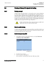
The solid lines designate the diagram applicable when the load current
compensation is active. The solid line and all test points except 13 are
valid for this case.
When the load current compensation is inactive, the dotted lines and
test point 13 are valid. Test points 5, 6, and 7 are not valid for this
measurement.
X1
X
R (Ohm/phase)
50%
80%
1
2
3
4
5
6
7
8
9
10
11
80% of RLdFw
40% of RLdFw
0.5 x RFPP
12
13
120°
20°
a
c
IEC05000368-3-en
b =
Ar
gLD
IEC05000368 V3 EN
Figure 14:
Distance protection characteristic with test points for phase-to-phase
measurements
Table 17:
Test points for phase-to-phase loops L1-L2 (Ohm/Loop)
Test point
Reach
Set value
Comments
1
X
X1
set
R
0
2
X
X1
set
R
R1
set
3
X
0.8 x X1
set
R
0.8 x R1
set
+ RFPP/2
4
X
0.5 x X1
set
R
0.5 x R1
set
+ RFPP/2
5
X
0.85 x RFPP x tan (ArgRLd)
ArgLd = angle for the maximal load
transfer
R
0.85 x RFPP
6
X
RLdFw x tan (ArgLd)
R
RLdFw
Table continues on next page
1MRK 506 355-UEN A
Section 10
Testing functionality by secondary injection
Line distance protection REL670 2.1 IEC
91
Commissioning manual
Summary of Contents for Relion 670 Series REL670
Page 1: ...Relion 670 series Line distance protection REL670 2 1 IEC Commissioning manual ...
Page 2: ......
Page 30: ...24 ...
Page 34: ...28 ...
Page 64: ...58 ...
Page 68: ...62 ...
Page 90: ...84 ...
Page 254: ...248 ...
Page 260: ...254 ...
Page 269: ...263 ...


