4.
Increase the injected current in phase L1 slowly by more than the set
I>
. No
signal shall be activated.
5.
Decrease the injected current in phase L1 to half the rated current.
6.
Increase the injected current in phase L1 in a step by more than the set
I>
. Start
and trip signal shall be activated.
10.11.7.4
Carrier receive logic LCCRPTRC
Prepare the IED for verification of settings as outlined in section
section
1.
Set
Operation
to
On
.
2.
Select
OpMode
according to the application: If two carrier channels are used and
high security shall be used set
OpMode
=
2 Out Of 2
, otherwise
1 Out Of 2
.
3.
Connect switchable binary signal/s CR1 and CR2 to the binary input/s to be used
for the carrier receive (CR) signal/s.
4.
Connect switchable binary signal/s to the binary input to be used for the local
check signal. If three pole trip is used only one LOCTR is used. If single pole trip
is used in addition the phase selective signals LOCTRL1, LOCTRL2and
LOCTRL3 are connected.
5.
Connect switchable binary signal/s to the binary input to be used for the
communication supervision signal/s CHERR1 and CHERR2.
If
OpMode
=
2 Out Of 2
:
6.
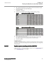
Activate input and check output signals according to table
.
Table 35:
Activate input signals if OpMode = 2 Out Of 2
INPut
CR1
X
X
X
X
X
X
CHERR1
X
CR2
X
X
X
X
X
CHERR2
X
LOCTR
X
X
X
LOCTRL1
X
LOCTRL2
X
LOCTRL3
X
Table 36:
Activate output signals if OpMode = 2 Out Of 2
OUTPut
Non
X
X
TRIP
X
X
X
X
X
TRL1
X
TRL2
X
TRL3
X
7.
Connect the trip output to a timer.
Section 10
1MRK 506 355-UEN A
Testing functionality by secondary injection
224
Line distance protection REL670 2.1 IEC
Commissioning manual
Summary of Contents for Relion 670 Series REL670
Page 1: ...Relion 670 series Line distance protection REL670 2 1 IEC Commissioning manual ...
Page 2: ......
Page 30: ...24 ...
Page 34: ...28 ...
Page 64: ...58 ...
Page 68: ...62 ...
Page 90: ...84 ...
Page 254: ...248 ...
Page 260: ...254 ...
Page 269: ...263 ...

