10.11.3.1
Current reversal logic
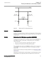
It is possible to check the delay of the CS send signal with
tDelayRev
by changing
from a reverse to a forward fault.
By continuously activating the CR input and changing from a reverse to a forward
fault, the delay
tDelayRev
can be checked.
Checking of current reversal
The reverse zone timer must not operate before the forward zone fault
is applied. The user might need to block the reverse zone timer setting
during testing of current reversal.
The forward zone timer must be set longer than the
tDelayRev
set
value.
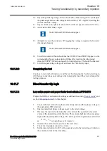
1.
Activate the receive (CRL) signal.
2.
Set the healthy condition to an impedance at 50% of the reach of the reverse zone
connected to IRV.
3.
After the start condition is obtained for reverse zone, apply a fault at 50% of the
reach of the forward zone connected to WEIBLK2.
4.
Check that correct trip outputs and external signals are obtained for the type of
fault generated. The operation time should be about the
tDelayRev
setting longer
than the carrier accelerated trip (TRIP) recorded for the permissive overreach
scheme communication.
5.
Restore the forward and reverse zone timer to its original setting.
10.11.3.2
Weak end infeed logic
Weak-end infeed logic at permissive overreach schemes
1.
Check the blocking of the echo with the injection of a CRL signal >40ms after
a reverse fault is applied.
2.
Measure the duration of the echoed CS signal by applying a CRL receive signal.
3.
Check the trip functions and the voltage level for trip by reducing a phase voltage
and applying a CRL receive signal.
Testing conditions
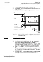
Only one type of fault is sufficient, with the current reversal and weak-end infeed logic
for distance protection function ZCRWPSCH. Apply three faults (one in each phase).
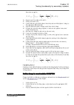
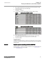
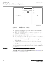
For phase L1-N fault, set these parameters:
1MRK 506 355-UEN A
Section 10
Testing functionality by secondary injection
Line distance protection REL670 2.1 IEC
215
Commissioning manual
Summary of Contents for Relion 670 Series REL670
Page 1: ...Relion 670 series Line distance protection REL670 2 1 IEC Commissioning manual ...
Page 2: ......
Page 30: ...24 ...
Page 34: ...28 ...
Page 64: ...58 ...
Page 68: ...62 ...
Page 90: ...84 ...
Page 254: ...248 ...
Page 260: ...254 ...
Page 269: ...263 ...


