background image

18 

5.4.2 Circuits

5.4.3 Print/Copy

5.5 Event 

Log

Software WIN-PC for Intrusion Alarm Panel L240

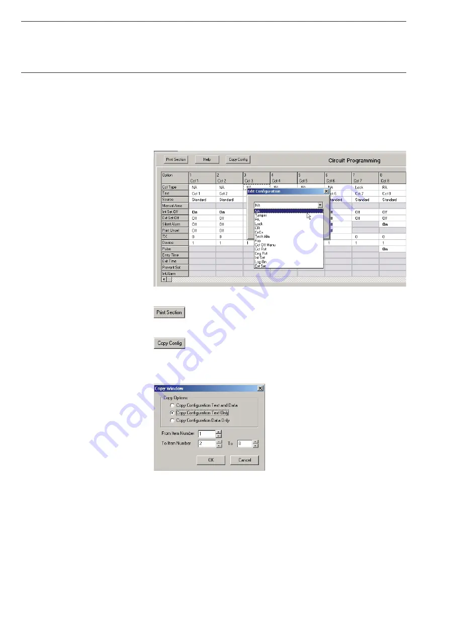
The figure below shows the detector circuit table “Circuit”. Depending on 
the circuit types or the set parameters, non-relevant fields are displayed 
with a grey background and cannot be edited. A double click on a field 
within the table opens a window with further entry options. In the example, 
a click was made on the “Cct Type” field. The selection corresponds with 
the Engineering edit menu “03=Circuits” on the Intrusion Alarm Panel 
L240. The text “

ON

” is bold for emphasis.


The entries made on the configuration page can be printed out 

as an overview using the “Print” button.


On some pages with comprehensive tables (Circuit, Keypad, 

User Auth, Area Text, Areas, Concs), the configuration of individual 
columns can be accepted onto other table sections via the button 
“Copy Config”.


In the example figure above:
Copy the texts from column 1 to columns 2 to 8.

In the “Event Log” window, the panel events are displayed in tabular form. 
The table indicates the index number, the date, the time and a description 
of the event that has occurred. Also shown is the user who has undertaken 
an operating step. Hereby, the users 1-8 correspond with the assigned 
user PINs, user 9 is the engineer and user 0 is the actual Intrusion Alarm 
Panel or the remote operation per WinPC. The update of the table is 
under taken via menu “Panel Connection”, sub point “Read Logs” and after 
clicking button “Read Event Log” (see chapter 5.7 Panel connection).

Summary of Contents for L240 Series

Page 1: ...Security Technology Software WIN PC for Intrusion Alarm Panel L240 Product Manual...

Page 2: ......

Page 3: ...8 4 First steps in WIN PC 10 4 1 Creating a customer account 10 4 1 1 Selection of connection type 11 4 1 2 Configuration file 11 4 1 3 Saving the customer file 11 4 2 Connection to the panel 12 5 Con...

Page 4: ...on Windows Vista must be deactivated Automatic installation starts as soon as the WIN PC msi file is run In the following the installation program will guide you through the installation WIN PC create...

Page 5: ...3 After successful login the WIN PC user interface starts WIN PC program window Software WIN PC for Intrusion Alarm Panel L240...

Page 6: ...operating structure of the panel L240 can be found in the manual Installation Commissioning Operation of the System L240 The Engineer level can be accessed from the base display Date Int Unset as foll...

Page 7: ...any time In order to establish the connection between the panel and the PC some of the parameters in the panel and PC must be set to ensure that they match one another In the Engineer level see the n...

Page 8: ...t can be found on the right side On the additional connection Keypad 0 a L840 PT with address 0 can be connected and used to program the Intrusion Alarm Panel or to enable the connected interface modu...

Page 9: ...for addressing the individual devices In the example configuration the following IP addresses are assumed can vary according to the network PC 192 168 3 1 L240 IP 192 168 3 3 Gateway 192 168 3 4 Gene...

Page 10: ...ec tion is activated and the type of communication is set Select Ethernet Connection Off On On Press button 1 to activate the connection Connection Type Ethernet Press button 2 for Type Ethernet Exit...

Page 11: ...irectly to the PC crossover cable the value 0 can be entered here Gateway IP 192 168 3 4 Entry of the gateway address Acknowledge the gateway IP with the Return button then exit the function 07 Gatewa...

Page 12: ...s Areas Number of areas Concs Number of circuit modules L240 B BS Number of electromechanical shunt locks modules Keypads Number of connected keypads SM V24 interface already installed see chapter 3 1...

Page 13: ...settings in the Intrusion Alarm Panel see figure Acknowledge the settings with OK IP LAN Ethernet Select the option IP in field Primary Route The IP number of the L240 IP is entered in the field Prima...

Page 14: ...this purpose press the Read Configuration button under Panel Connection in the submenu Configuration The transfer may take a few minutes depending on the amount of data to be transferred Note After r...

Page 15: ...13 In order to close the connection press button Disconnect in the Panel Connection window Software WIN PC for Intrusion Alarm Panel L240...

Page 16: ...ter selection of the Customer List the table Customer Details appears in the main window The columns specify the GSR ID the Customer Name the Customer Address and the Panel Type firmware version A dou...

Page 17: ...entries must be saved using the Save button to complete the editing of the customer account If you click in the customer tree on Configuration the configuration window opens and you have the option o...

Page 18: ...new panel firmware to software version L240_V440_UK The configuration files can be compared with one ano ther in the window that opens In the Existing Versions field you can see existing files alread...

Page 19: ...individual points for configuration of the L240 are described in detail in the manual of the Intrusion Alarm Panel in chapter Configuration and programming by the commissioning engineer In the followi...

Page 20: ...he Print button On some pages with comprehensive tables Circuit Keypad User Auth Area Text Areas Concs the configuration of individual columns can be accepted onto other table sections via the button...

Reviews: