background image


11

Software WIN-PC for Intrusion Alarm Panel L240

4.1.1  

Selection of connection type

4.1.2  

Configuration file

4.1.3  Saving the customer file

The following options are available for selection of the connection type:
•  No Route 
•  DIRECT#1 (Serial interface/V24) 
•  IP (LAN/Ethernet)

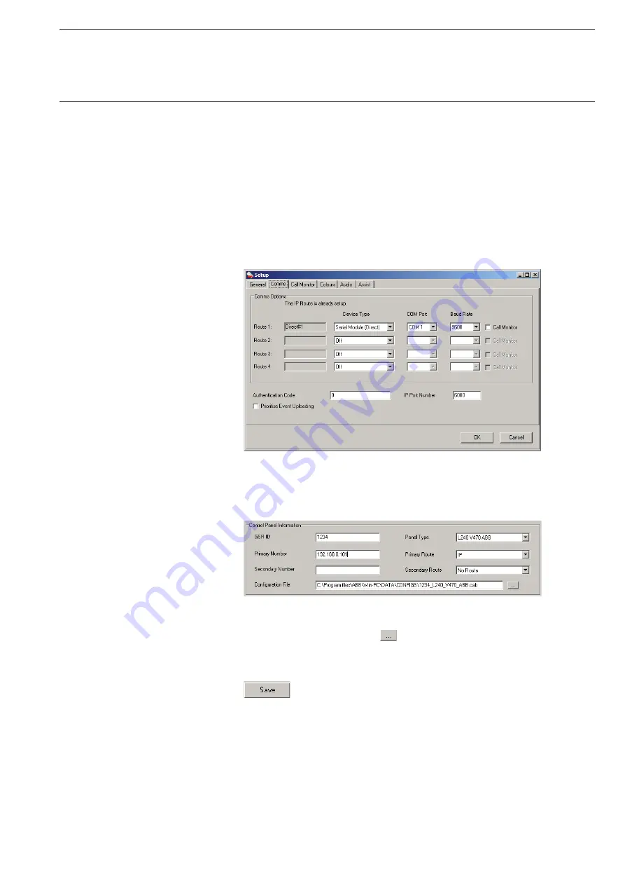
DIRECT#1 (Serial interface/V24 interface)

The option “DIRECT#1” for the V24 connection only appears if the para-
meters for the serial connection have been defined. For this purpose go to 
the “Tools-View Setup” menu bar. In the Setup window, you can define the 
corresponding parameters under “Comms” to comply with the settings in 
the Intrusion Alarm Panel (see figure). Acknowledge the settings with “OK”.

IP (LAN/Ethernet)

Select the option IP in field “Primary Route”. 
The IP number of the L240/IP is entered in the field “Primary Number”.

The configuration file required for saving the customer configuration is 
created by pressing button “ 


”. In the window that then opens, you are 

offered the option of creating a new file or selecting an existing file.


When complete the “Customer account” must be saved. 

Click on the “Save” button for this purpose. If you have not defined a con-
figuration file, WIN-PC asks if you want to use a default name. The default 
name has the format: <customer number_panel type.cab>.

By default the customer data is stored on the PC at the following location: 
C:\Programs\ABB\Win-PC\DATA\CONFIGS

Summary of Contents for L240 Series

Page 1: ...Security Technology Software WIN PC for Intrusion Alarm Panel L240 Product Manual...

Page 2: ......

Page 3: ...8 4 First steps in WIN PC 10 4 1 Creating a customer account 10 4 1 1 Selection of connection type 11 4 1 2 Configuration file 11 4 1 3 Saving the customer file 11 4 2 Connection to the panel 12 5 Con...

Page 4: ...on Windows Vista must be deactivated Automatic installation starts as soon as the WIN PC msi file is run In the following the installation program will guide you through the installation WIN PC create...

Page 5: ...3 After successful login the WIN PC user interface starts WIN PC program window Software WIN PC for Intrusion Alarm Panel L240...

Page 6: ...operating structure of the panel L240 can be found in the manual Installation Commissioning Operation of the System L240 The Engineer level can be accessed from the base display Date Int Unset as foll...

Page 7: ...any time In order to establish the connection between the panel and the PC some of the parameters in the panel and PC must be set to ensure that they match one another In the Engineer level see the n...

Page 8: ...t can be found on the right side On the additional connection Keypad 0 a L840 PT with address 0 can be connected and used to program the Intrusion Alarm Panel or to enable the connected interface modu...

Page 9: ...for addressing the individual devices In the example configuration the following IP addresses are assumed can vary according to the network PC 192 168 3 1 L240 IP 192 168 3 3 Gateway 192 168 3 4 Gene...

Page 10: ...ec tion is activated and the type of communication is set Select Ethernet Connection Off On On Press button 1 to activate the connection Connection Type Ethernet Press button 2 for Type Ethernet Exit...

Page 11: ...irectly to the PC crossover cable the value 0 can be entered here Gateway IP 192 168 3 4 Entry of the gateway address Acknowledge the gateway IP with the Return button then exit the function 07 Gatewa...

Page 12: ...s Areas Number of areas Concs Number of circuit modules L240 B BS Number of electromechanical shunt locks modules Keypads Number of connected keypads SM V24 interface already installed see chapter 3 1...

Page 13: ...settings in the Intrusion Alarm Panel see figure Acknowledge the settings with OK IP LAN Ethernet Select the option IP in field Primary Route The IP number of the L240 IP is entered in the field Prima...

Page 14: ...this purpose press the Read Configuration button under Panel Connection in the submenu Configuration The transfer may take a few minutes depending on the amount of data to be transferred Note After r...

Page 15: ...13 In order to close the connection press button Disconnect in the Panel Connection window Software WIN PC for Intrusion Alarm Panel L240...

Page 16: ...ter selection of the Customer List the table Customer Details appears in the main window The columns specify the GSR ID the Customer Name the Customer Address and the Panel Type firmware version A dou...

Page 17: ...entries must be saved using the Save button to complete the editing of the customer account If you click in the customer tree on Configuration the configuration window opens and you have the option o...

Page 18: ...new panel firmware to software version L240_V440_UK The configuration files can be compared with one ano ther in the window that opens In the Existing Versions field you can see existing files alread...

Page 19: ...individual points for configuration of the L240 are described in detail in the manual of the Intrusion Alarm Panel in chapter Configuration and programming by the commissioning engineer In the followi...

Page 20: ...he Print button On some pages with comprehensive tables Circuit Keypad User Auth Area Text Areas Concs the configuration of individual columns can be accepted onto other table sections via the button...

Reviews: