4 Repair
4.6.1. Replacement of motor, axis 1
223
3HAC028197-001 Revision: A
©
Co
py
rig
h
t 200
7-
200
8 ABB. All righ
ts reser
v
ed.
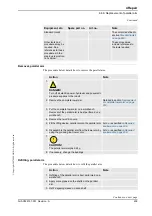
Removal, motor
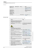
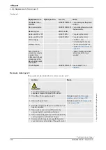
The procedure below details how to remove motor, axis 1.
Other tools and
procedures may be
required. See
references to these
procedures in the
step-by-step
instructions below.
These procedures include
references to the tools
required.
Circuit diagram
3HAC025744-001
See chapter
Circuit
diagram
.
Equipment, etc
Spare part no.
Art.no.
Note
Action
Note
1.
DANGER!
Turn off all electric power, hydraulic and
pneumatic pressure supplies to the robot!
2. Remove the
motor cover
in order to get access
to the connectors on top of the motor by
unscrewing its four attachment screws.
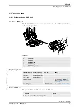
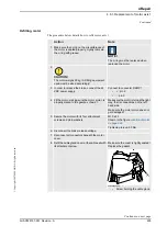
Shown in the figure
xx0600002696
•
A: Motor cover
•
B: Attachment screws
•
C: Cable gland
Continued
Continues on next page
Summary of Contents for IRB 6660 - 130/3.1
Page 1: ...Product manual Articulated robot IRB 6660 130 3 1 IRB 6660 205 1 9 M2004 ...
Page 2: ......
Page 332: ... 0 1 23 3 4 5 5 6 2 70 2 888 2 9 6 0 9 9 2 A 8B C D 9 8 B ...
Page 333: ... 2 3 4 5 5 6 2 70 2 888 2 9 6 0 9 9 1 EF 2 888 2 9 6 9 9 8 B ...
Page 336: ... 98 2 888 7 066 0 10I 4 5 5 06 6 2 70 2 888 2 9 6 0 9 9 G E 7 F E 7 F 9 8 B ...
Page 347: ......

