


5 Calibration information
5.3. Calibration scales and correct axis position
413
3HAC023082-001 Revision: E
©
Co
py
rig
h
t 200
4-
200
8 ABB. All righ
ts reser
v
ed.
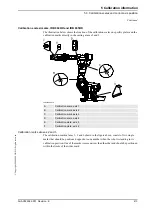
Calibration scales/ marks, IRB 6600ID and IRB 6650ID
The illustration below shows the location of the calibration scales on specific plates and the
calibration marks directly in the casting at axes 2 and 3.
xx0500002016
Calibration marks at axes 2 and 3
The calibration marks at axes 2, 3 and 6 shown in the figure above, consist of two single
marks that should be positioned opposite to one another when the robot is standing in its
calibration position. One of the marks is more narrow than the other and should be positioned
within the limits of the wider mark.
A
Calibration scale, axis 1
B
Calibration mark, axis 2
C
Calibration mark, axis 3
D
Calibration scale, axis 4
E
Calibration plate, axis 5
F
Calibration plate, axis 6
Continued
Summary of Contents for IRB 6600 - 175/2.8 type B
Page 2: ......
Page 10: ...Table of Contents 8 3HAC023082 001 Revision E Copyright 2004 2008 ABB All rights reserved ...
Page 532: ......