4 Repair
4.4.7. Securing the lower arm
307
3HAC023082-001 Revision: E
©
Co
py
rig
h
t 200
4-
200
8 ABB. All righ
ts reser
v
ed.
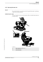
Securing the lower arm
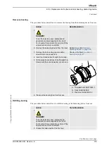
The procedure below details how to secure the lower arm by fitting the fixture to the robot.
Action
Note/Illustration
1.
DANGER!
Turn off all electric power, hydraulic and pneumatic
pressure supplies to the robot!
For Foundry Prime robots: Do not turn off the air
pressure to motors and SMB.
2. Remove any load or equipment fitted to the upper
arm or turning disk.
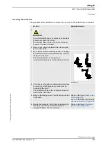
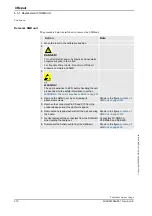
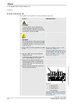
3. Move the robot to the calibration position. The upper
arm can be directed in three different ways, shown in
the figure to the right.
The lowered position, as in figure A, is
recommended as it gives the least load on the tool.
xx0200000260
4. If the robot is fitted with moveable mechanical stops
on axis 2 (not stock equipment), these must be
removed at this point.
The attachment holes of the mechanical stops are
used to attach the fixture.
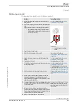
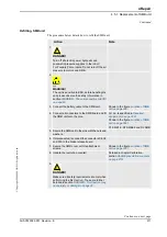
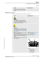
5. Remove the
locking screw
from the fixture, where it
is attached.
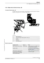
Shown in the figure
Art. no. of the fixture is specified in
Required equipment on page 306
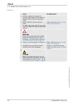
6. Secure the lower arm to the frame by inserting the
locking screw into a specific
attachment hole
through the frame, into the lower arm.
Shown in the figure
Continued
Continues on next page
Summary of Contents for IRB 6600 - 175/2.8 type B
Page 2: ......
Page 10: ...Table of Contents 8 3HAC023082 001 Revision E Copyright 2004 2008 ABB All rights reserved ...
Page 532: ......


