5 Electrical Interconnections Converter
D184B122U02
S4
19
5.8
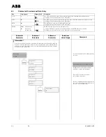
Interconnection Examples Peripherals with PROFIBUS PA
Fig. 10:
Interconnection Examples for Peripherals with PROFIBUS PA
97
98
R
C
PA-
PA+
Bus Cable
PROFIBUS PA
internal
external
1
2
3
4
M3
M1
FRAM
41
42
97
98
U+
2S
1
1S
U-
3
3
2
16
6
7
PROFIBUS PA
The resistance R and the capacitor C form
the bus termination. They are to be installed
if the instrument is connected at the end of
the bus.
R = 100 Ohm; C = 1 µF
Contact output see Page 18
Bus termination in converter S4
To terminate the bus if the instrument is at the end of the bus cable, the termination components in
the converter S4 can be used. To accomplish this, close both hook switches in the connection area
of the converter.
Important!
If the converter module is removed, the bus termination is also removed.
Interconnection Example for PROFIBUS PA using M12-Plug (option)
Pin designations
(View from the front onto the pin insert and
pins)
PIN 1 = PA
PIN 2 = nc
PIN 3 = PA-
PIN 4 = Shield
Connections using the M12-Plug (only for PROFIBUS PA design)
As an option, the bus termination can be made using the M12-plug instead of the cable connector
(see Ordering Information for the instrument).
The instrument is then shipped completely wired. Suitable receptacles (Type EPG300) together with
other accessories may be found in the List Sheet 10/63.6.44DE.
Close hook switches for
bus termination


