


5 Electrical Interconnections Converter
D184B122U02
S4
15
5.5.2
Flowmeter Primary with Preamplifier DN 1 to DN 1000 [1/25” to 40”]
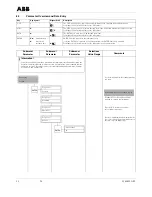
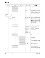
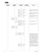
Fig. 6:
Interconnection Diagram DN 1 - DN 8[1/25” - 5/16”] and DN 10 - DN 1000 [3/8” - 40”] with Preamplifier
2-
L
M3 M1
32
31
51 52
41
N
1+
1)
2)
3)
4)
82
1
U+
2
16
U-
3
42
6)
7)
U+
3
U-
16
3
SE
M3 M1 SE
3
81
24 V
+
-
5)
1
2
Earth
Earth
Converter S4
Wall Mount Housing
Flowmeter Primary
With preamplifier
(always for DN1–DN8
[1/25”-5/16”)
Comment:
We recommend that shielded output cables be used with the shields connected to earth at one end.
!
Attention!
If the flowmeter primary includes a preamplifier for low conductivity of for small flow-
meter size DN 1 to DN 8 [1/25” to 5/16”], then the voltage supply ±12 V DC must be
connected to the terminals U+ and U- and be connected to the flowmeter primary as
well as at the converter.
1)
Supply Power
High voltage:
Low voltage:
Frequency:
AC 85–253V
Terminals L, N,
AC 20.4 to 26.4 V
DC 20.4 to 31.2 V
Terminals 1+, 2-,
47 Hz
≤
f
≤
53 Hz; 50 Hz supply power
56 Hz
≤
f
≤
64 Hz, 60 Hz supply power
2)
Magnet Coil Supply:
Shielded 2 x 1 mm² CE Typ 227 TEC 74
ABB Part No. D173D147U01
10 m included in shipment Standard
3) – 6) Output Cables
See Page 18
7)
Shielded Signal Cable:
ABB Part No. D173D018U02, 10 m included in shipment.


