91
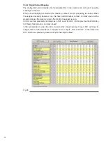
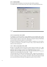
14.8.2.1 Digital Output meanings
Output contact to signal CB position, contact closes when CB status = closed
Output contact to signal CB position, contact closes when CB status = open
Output contact to signal CB truck position, contact closes when CB truck status =
inserted
Output contact to signal CB truck position, contact closes when CB truck status =
withdrawn
Output contact to signal LD position, contact closes when LD status = closed
contact closed when LD status = open
contact closed when LD status = closed to earth
Output contact to signal ES position, contact closes when ES status = open
contact closed when ES status = closed to earth
Output contact to signal logical condition of IED ready: no microprocessor failure, coil
continuity ok, capacitor charged, no position incongruence, no failure anomaly, contact
closes when the IED status = Ready
Negation of logical condition of IED ready, contact closes when the IED status = Not
Ready
Output contact to signal presence of an anomaly condition, depending on its seriousness,
it can cause the not Ready condition. Contact closes when at least one Anomaly is
present
Fixed output to enable safety lock of truck position depending on CB status. Only when
CB is open and ready and the DI (Digital input) Earting switch open is high = 1 = present,
enabling supply to the –RL2 locking magnet and to rack the CB out or in. If the digital
Earthing Switch open is flagged on the “Input mapping” page, the IED assumes that it is
present and high.
General protection trip, contact closes when at least one protection function associated
in the Logic Configuration Tab goes into trip status.
General protection start, contact closes when at least one protection function associated
in the Logic Configuration Tab goes in start status.
General protection start, contact closes when at least one protection function associated
in Logic Configuration Tab goes into start status.
General protection trip, contact closes when at least one protection function associated
in the Logic Configuration Tab goes into trip status.
Output contact to signal CB was opened due to Undervoltage function; contact closes
when UnderVoltage performs CB opening and stays latched until the Anomaly is reset.
When the CB is closed again (close allowed) while UV is active, the BO stays closed.
Output contact to signal CB was opened due to an open command from remote; contact
closes when the IED performs CB opening and stays closed for 100ms
General protection start, contact closed when at least one protection function associated
in the Logic Configuration Tab goes into start status.
General protection start, contact closes when at least one protection function associated
in the Logic Configuration Tab goes into start status.
Output contact to signal CB Open Disabling function is active (function ticked and DI
low). The CB is locked in the closed position and the LED on the local CB HMI is on
Output contact to signal CB Closing Disabling function is active (function ticked and DI
low). The CB is locked in the open position and the LED on the local CB HMI is on
Output contact to signal IED control mode is Local. The LED on the local CB HMI is on
Output contact to signal IED control mode is Remote. The LED on the local CB HMI is off
Output contact to signal whem the namesakeinput becomes low for at least 5s
Output contact to signal a µP failure, high reliability HW circuit only. Contact is closed
when the IED is not supplied and open when supplied and functional. It will close again
on IED µP failure.
CB closed
CB open
CB in Service position
CB in Test position
Line disconnector closed
Line disconnector open
Line disconnector closed to
earth
Earthing Switch open
Earthing Switch closed
Unit Ready
Unit Not Ready
Anomaly
Output for Truck Locking
Magnet (-RL2)
Protection Trip 1
Protection Start 1
Protection Start 2
Protection Trip 2
CB Opened for underVoltage
CB Opened Transient
Contact
Interlock Output 1
Interlock Output 2
# CB Opening Disabled
# CB Closing Disabled
Local Mode
Remote Mode
Auxiliary supply monitoring
WatchDog Not Ready
Summary of Contents for eVM1
Page 1: ...eVM1 Installation and service instructions 12 17 5 kV 630 1250 A 16 31 5 kA ...
Page 2: ...1 ...
Page 76: ...74 Fig 66 Fig 67 ...
Page 77: ...75 Fig 68 Fig 69 ...
Page 110: ...108 Notes ...
Page 111: ...1 ...


