71
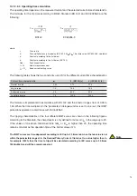
When Ie is measured directly (by ticking CCT presence box under “General settings”) Start Value
begins from 0,05 Ien.
14.7.2.4.1 Measurement mode
Earth fault IDMT protection function evaluates the RMS residual current at the fundamental frequency
in two ways:
direct measurement of earth fault current at the dedicated analog input via an external residual
current transformer, or
neutral current calculated by the vectorial sum of the three phase currents.
Ticking the CCT presence box in the General Settings enables the direct measurement mode.
14.7.2.4.2 Operation criteria
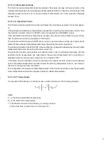
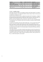
If the measured or calculated RMS earth current exceeds the setting threshold value (Base current
Ieb) by a factor of 1.2, the protection function is started.
The protection function will return to passive status and the start signal will be cleared if the earth
current falls below 115% of the setting threshold value.
When the protection enters the start status, the operating time is continuously recalculated according
to the set parameters and earth fault current value. If the calculated operating time is exceeded,
the function goes into TRIP status and the trip signal becomes active.
The operating time depends on the measured current and the selected current-time characteristic.
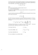
The formulas for the trip time according to British Standard (BS 142) and IEC 60255-3 are reported
in chapter: IDMT Protection Time-Current Characteristics.
The protection function will exit the TRIP status, the trip signal and the counter will be cleared
when the measured or calculated earth current value falls below 40% of the setting threshold
value.
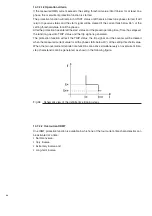
The earth fault overcurrent time-step characteristic shown in the next figure is obtained when the
two definite time functions are combined with the IDMT. The IDMT function is generally used to
provide low current protections with an exponential characteristic threshold.
Fig. 64
Schematic view of the earth fault definite time and IDMT tripping characteristic
Summary of Contents for eVM1
Page 1: ...eVM1 Installation and service instructions 12 17 5 kV 630 1250 A 16 31 5 kA ...
Page 2: ...1 ...
Page 76: ...74 Fig 66 Fig 67 ...
Page 77: ...75 Fig 68 Fig 69 ...
Page 110: ...108 Notes ...
Page 111: ...1 ...


