6
A
1
3
2
3
D
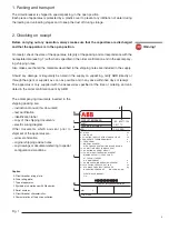
Fig. 2
3. Storage
When a period of storage is foreseen, our workshops can (on request) provide suitable packing
for the specified storage conditions.
On receipt the apparatus must be carefully unpacked and checked as described in Checking on
receipt (chap. 2).
If immediate installation is not possible, the packing must be replaced, using the original material
supplied.
Insert special hygroscopic substances inside the packing, using at least one standard packet per
piece of apparatus.
Should the original packing not be available and immediate installation is not possible, store in a
covered, well-ventilated, dry, dust-free, non-corrosive ambient, away from any flammable materi-
als and at a temperature between –5 °C and +45 °C.
In any case, avoid any accidental impacts or positioning which stresses the structure of the appa-
ratus.
4. Handling
Before carrying out any operations, always make sure that the capacitors are discharged.
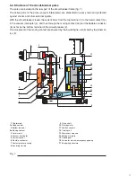
To lift and handle the circuit-breaker, proceed as follows (fig. 2):
– use a special lifting tool (1) (not supplied) fitted with ropes with safety hooks (2);
– insert the hooks (2) in the supports (3) fixed to the frame of the circuit-breaker and lift. Latch the
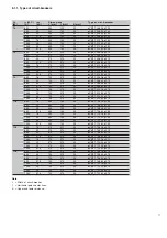
hooks (2) into the support holes (3) according to the type of apparatus (see table);
– on completion of the operation (and in any case before putting into service) unhook the lifting
tool (1) and dismantle the supports (3) from the frame.
During handling, take great care not to stress the insulating parts and the terminals of the circuit-
breaker.
Version
Pole centre Rated
Hole
distance
current
Fixed
150 mm
up to 1250 A
A
Fixed
210 mm
up to 1250 A
A
Fixed
275 mm
up to 1250 A
A
Withdrawable
150 mm
up to 1250 A
A
Summary of Contents for eVM1
Page 1: ...eVM1 Installation and service instructions 12 17 5 kV 630 1250 A 16 31 5 kA ...
Page 2: ...1 ...
Page 76: ...74 Fig 66 Fig 67 ...
Page 77: ...75 Fig 68 Fig 69 ...
Page 110: ...108 Notes ...
Page 111: ...1 ...


