5.0 CIRCUIT DESCRIPTION
5.1 Meter Signals
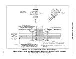
The meter body houses two signal electrodes and two flux producing magnet coils. All meter
intraconnection wiring is terminated at the CMC/ZERO pc board located in the base of the meter
housing.
The meter provides two output signals to the associated signal converter; one, an electrode signal
that contains the flow rate information, and two, the reference signal which is proportional to the
magnet excitation current (theoretically, this reference signal is proportional to the flux density in the
metering section). The reference voltage is derived across a precision "constant meter factor"
resistance network that is connected in series with the magnet coils. Changes in magnet drive
voltage, which cause a variation of flow signal, will simultaneously cause a proportional variation of
the reference voltage. The circuitry will provide an exact ratio and thereby provide immunity to power
supply variation. The magnet coil drive circuitry is contained in the signal converter.
5.2 Constant Meter Capacity (CMC) PC Assembly
The CMC pc assembly provides the following functions:
1. Establishes interconnections between the meter internal wiring and the signal
converter.
2. Permits factory adjustment of meter capacity values to a fixed value for each nominal size
meter.
3. Permits factory adjustment of meter zero.
4. Aligns the phase of the electrode and reference signals.
10DS3111E INSTRUCTION MANUAL
5-1

