


2.6 Electrical Interconnection
The Series 3000 Magnetic Flowmeter is furnished with a remotely mounted Signal Converter.
Interconnection details are provided in the Instruction Bulletin provided with the Signal Converter.
WARNING
ELECTRICAL SHOCK HAZARD. Equipment powered by ac line voltage
constitutes a potential electric shock hazard to the user. Make certain
that the system power input leads are disconnected from the operating
branch circuit before attempting electrical interconnections.
The cable from the remote converter is connected to the Primary using the customer connection box
mounted on the meter body. FIGURE 3-2 shows the customer connection circuit board located inside
the customer connection box. The signal cable from the remote converter is connected to the meter
using the terminal blocks labeled "CUSTOMER CONNECTIONS" shown in FIGURE 3-2.
When incorporating the interconnection procedures, the grounding procedures given in Section 2.5
must be followed.
For explosion proof meter installation, all interconnection wiring must be installed according to
National Electrical Code (NEC) ANSI/NFPA 70 Section 500.
NOTE
For meters capable of continuous submergence, the signal ca-
ble has been permanently installed by the factory. Do not
loosen the cable seal fitting or remove the connection box lid
since this will break the seal and void the warranty.
2.7 Conduit Seal and Pressure Relief
In accordance with the National Electrical Code (NEC) ANSI/NFPA 70, Article 501-5(f)(3), the
flowmeter includes a conduit entry seal and pressure relief to prevent the process liquid from entering
the electrical conduit system. This safety feature considers the remote possibility of a primary seal
failure, in which case, the secondary seal will prevent the process from entering the electrical conduit
system.
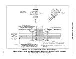
It is the user’s responsibility to properly install the conduit entry cable seal fitting supplied with the
signal cable provided with the remotely mounted signal converter. This will ensure proper perform-
ance of this safety feature. Refer to Figure 2-18.
A pressure relief is provided in the electronics housing in the customer connection box on the meter.
The pressure relief is located in the center of the housing joint on the side opposite from the conduit
connection. If the primary seal should fail, the pressure relief will vent the process preventing an over
pressurization and potentially dangerous failure of the electronics housing.
It is the user’s responsibility to be aware of this safety feature and to consider the unlikely event of its
functioning. Based on knowledge of the process and meter application, the user should consider the
installation orientation of the meter and possible use of deflectors to safely direct the vented process.
10DS3111E INSTRUCTION MANUAL
2-23


