CBV-2U4-3T(-N) |
Control Sequence Overview
©ABB 2022 All Rights Reserved.
Subject to change without notice
WWW.CYLON.COM
59
M
AN0
13
9
re
v
14
VARIABLE SPEED FAN
The terminal unit fan speed will be controlled through
AO-15
(0
…
10 V dc, 2
…
10 V dc, or a custom range).
When initially powered up, or upon restoration of power after a power outage, the
CBV-2U4-3T(-N)
controller
executes a fan startup sequence to prevent reverse rotation. The fan startup sequence drives the primary air
damper closed, waits 30 seconds, and then sets the fan speed output to 100% for 2 seconds. The controller
will then set the fan speed output to the current fan setpoint,
(A176.)
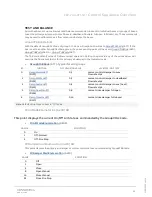
Fan Speed Calculation
(A176) is determined by translating the current Cool or Heat
demand percent to the range from min to max fan speed. For instance, with a Cooling demand of 50% and
a series fan with a min (deadband) fan speed setpoint of 20% and a maximum (cool stpt) fan speed setpoint
of 70%,
(A176) is calculated as follows:
Fan Speed Setpoint Range: 70 % max
–
20 % min = 50 %
Cool Demand = 50 %
50 % demand X 50 % range = 25% signal
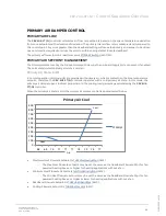
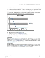
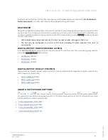
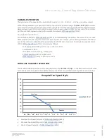
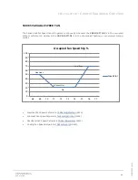
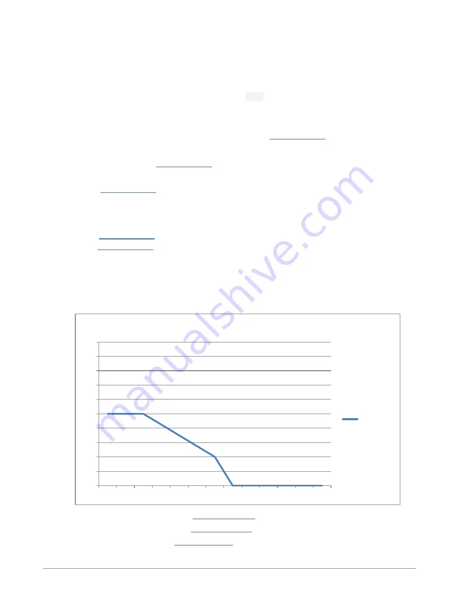
PARALLEL VARIABLE SPEED FAN
The Parallel Variable Speed fan will be energized when the
CBV-2U4-3T(-N)
is in the heat mode and off when
not in the heat mode. Speed will modulate between the Minimum and Maximum Setpoints as shown below.
•
Max Heat Fan Speed Setpoint is
•
Min Heat Fan Speed Setpoint is
(A154)
•
Min Fan Speed Setpoint is
(A224)
0
10
20
30
40
50
60
70
80
90
100
68 68.5 69 69.5 70 70.5 71 71.5 72 72.5 73 73.5 74
Occupied Fan Speed Stp %
Speed Stpt
Max Heat
Min
Heat
Deadba
nd
Summary of Contents for CBV-2U4-3T
Page 1: ... USER GUIDE MAN0139 rev 14 CBV 2U4 3T N ...
Page 75: ......


