


CBV-2U4-3T(-N) |
Installation Overview
©ABB 2022 All Rights Reserved.
Subject to change without notice
WWW.CYLON.COM
11
M
AN0
13
9
re
v
14
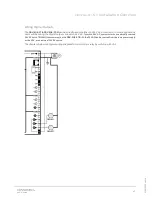
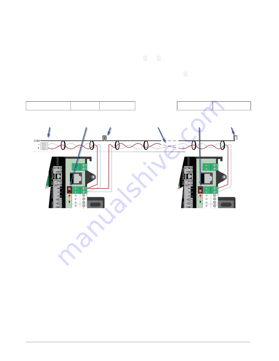
Wiring the RS-485 Network
Wiring the
RS-485
network involves connecting the
A+
and
B-
terminals in a daisy-chained configuration. One
end of the network will be connected to the subnet of the Target or fieldbus of router. At the other end of the
network,
the last device must be “terminated” by either installing a 100 ohm to 120
-ohm resistor or, if the last
device is a
CBV-2U4-3T(-N)
, users
can switch the “
Fieldbus Terminator
” to
on
. This will effectively terminate the
network. The shield, or drain wire, must be carried through the entire network. If the
RS-485
network is wired
to a Target, then the shield will be grounded at the Target. If it is wired to a router, the shield must be grounded
at one point on the network as shown below:
Network-level Controller or
Router
CBV-2U4-3T(-
N)
Network Segment
end
- - - - - -
CBV-2U4-3T(-N)
Network end
Shield connected at end
of network only
Network
Termination
switch set to
OFF
Shield continuous
throughout the
network
Network cable segment
daisy-chained to next
device
Network
Termination switch
set to ON at end of
network
Shield connected to
earth at one end of
network only
Summary of Contents for CBV-2U4-3T
Page 1: ... USER GUIDE MAN0139 rev 14 CBV 2U4 3T N ...
Page 75: ......


