B2342
Emax VF
43/66
Doc. No
Model
Apparatus
Scale
Page No
1SDH000909R0001
12.3.5.3. Modules
In this section it is possible to set the Module parameters.
All parameters are available only with unit present. COM module refers to PR120/D-M (Communication module); SIGNALLING module
refers to PR120/K (Signalling module).
Module
Setting
Range
Description
COM
module
Local/Remote
Local / Remote
The change of parameters setting by user is available on
display menu, or using external communication.
Serial Address
1...247 (step 1)
Set the address
Baud rate
9600 bit/s / 19200 bit/s
Set the Baud rate
Physical protocol
8,E,1 / 8,O,1 / 8,N,2 / 8,N,1
Set the kind of byte for communication (N°bit, Parity, stop
bit).
Addressing
Modbus standard / ABB
Set the address for communication.
SIGNALLING
module
Relay n.1
- Signal Source: list
- Delay: 0.01s...100s (step 0.01s)
- Status: NO / NC
- Latched: ON / OFF
- Allow selection of events to associate with each contact.
- Set the changing status delay of contact.
- Set the normal status of the contact.
- Set the possibility to reset or to mantain the contact in
the ON position after an event.
Relay n.2
Relay n.3
Relay n.4
Input
- Polarity: active low / high
- Function: list
- Delay: 0.01s...100s (step 0.01s)
- Allow selection of the input status.
- Allow selection of the events to associate to the input
presence.
- Set the event delay associated to input.
For more details refer to the description of the module, starting from para. 12.4.
WARNING: With unit in Remote status, all parameters and settings are in read-only mode, except for the setting
Local / Remote (available to user).
With unit in Local status, all parameters and settings are in read-only mode.
WARNING: Use the address “modbus Standard” only
12.3.5.4. Datalogger
On this section is possible to set the Datalogger function parameters.
The data logger function can be used to save the instantaneous values of certain analog and digital measurements automatically in
a large-sized memory buffer. The data can easily be downloaded from the unit using either application with external module (BT030-
USB and Ekip T&P) or optional module (PR120/D-M), and transferred to any personal computer for processing.
The function allows the event to be set for recording stop, the sampling frequency and the stop delay, in order to facilitate failure analysis.
Setting
Range Value
Description
Presence
Enable / Disable
Determines the presence of the protection.
Sampling Frequency
600Hz / 1200Hz / 2400Hz / 4800Hz Determines the Sampling frequency of the signals
Stop Event
List
Allow selection of the event for recording stop for storage
Stop Delay
0s...10s (step 0.01s)
Allow setting a delay for the recording
Restart
Command
Allow reset of data recorded, and to restart the datalogger
Stop
Command
Stop recording.
By using Ekip Connect software it is possible to download the recording and to read the data.
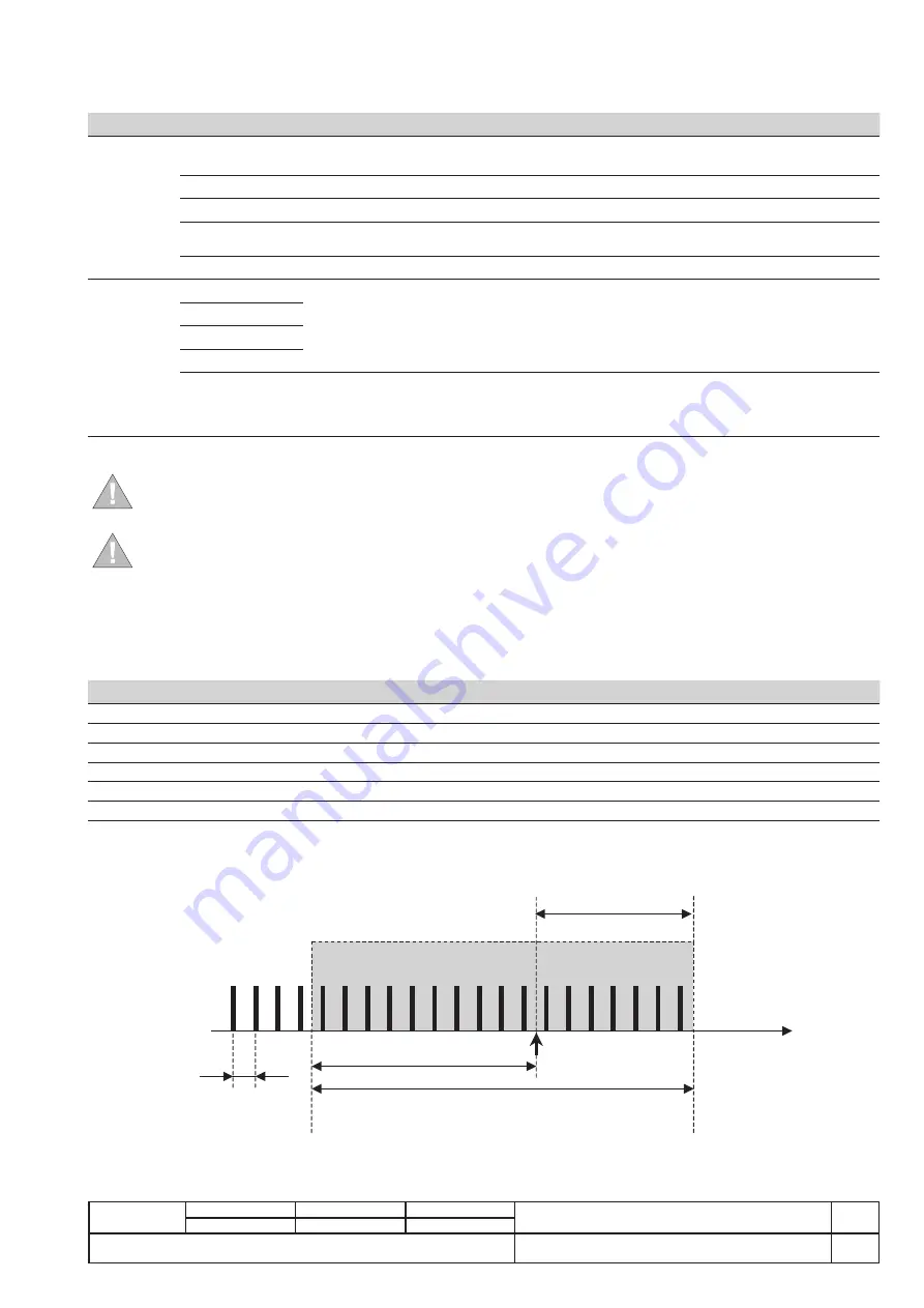
The data logger measurements are recorded in a time window, the duration of which is defined and synchronized by an event (trigger/
stop event) of your choice. The following figure displays the time window, the trigger and the samples available in grey:
Stopping
delay
Measurements available
Pretrigger
Samples
1/Freq
Trigger
Recording time


