B2342
Emax VF
35/66
Doc. No
Model
Apparatus
Scale
Page No
1SDH000909R0001
12.1.3.2. Power Supply specifications
Unit PR122/VF checks the presence of the auxiliary power supply (AUX); in case of AUX not being present and with the unit supplied
by external module as BT030-USB, an alarm condition is shown:
Auxiliary voltage
24V DC ±20%
Maximum ripple
5%
Inrush current
~10 A for 5ms (max)
Rated power (without module PR120/D-M and PR120/K)
~3W (max)
Rated power (with module PR120/D-M and PR120/K)
~5W (max)
WARNING: The external auxiliary power supply (AUX) must be always provided to the trip unit: without AUX, the
trip unit does not work, and the CB is not protected.
It is recommended to use a backup battery to guarantee the presence of the AUX, or to add to the circuit breaker
an undervoltage release (YU) to open the CB if AUX is not present.
The AUX must be supplied by using a galvanically-separated power pack:
WARNING: Since the auxiliary voltage needs to be isolated from the ground, “galvanically separated converters”
must be used, in accordance with the IEC standard 60950 (UL 1950) or the equivalent IEC 60364-41 and CEI 64-
8, to guarantee a current in common mode or leakage current (as defined in IEC 478/1 and CEI 22/3) no greater
than 3.5mA.
The Connection of AUX must be made with a two-pole shielded twisted cable (example: BELDEN 3105A/3105B).
WARNING: The unit PR122/VF display backlight will be ON only with AUX within required range.
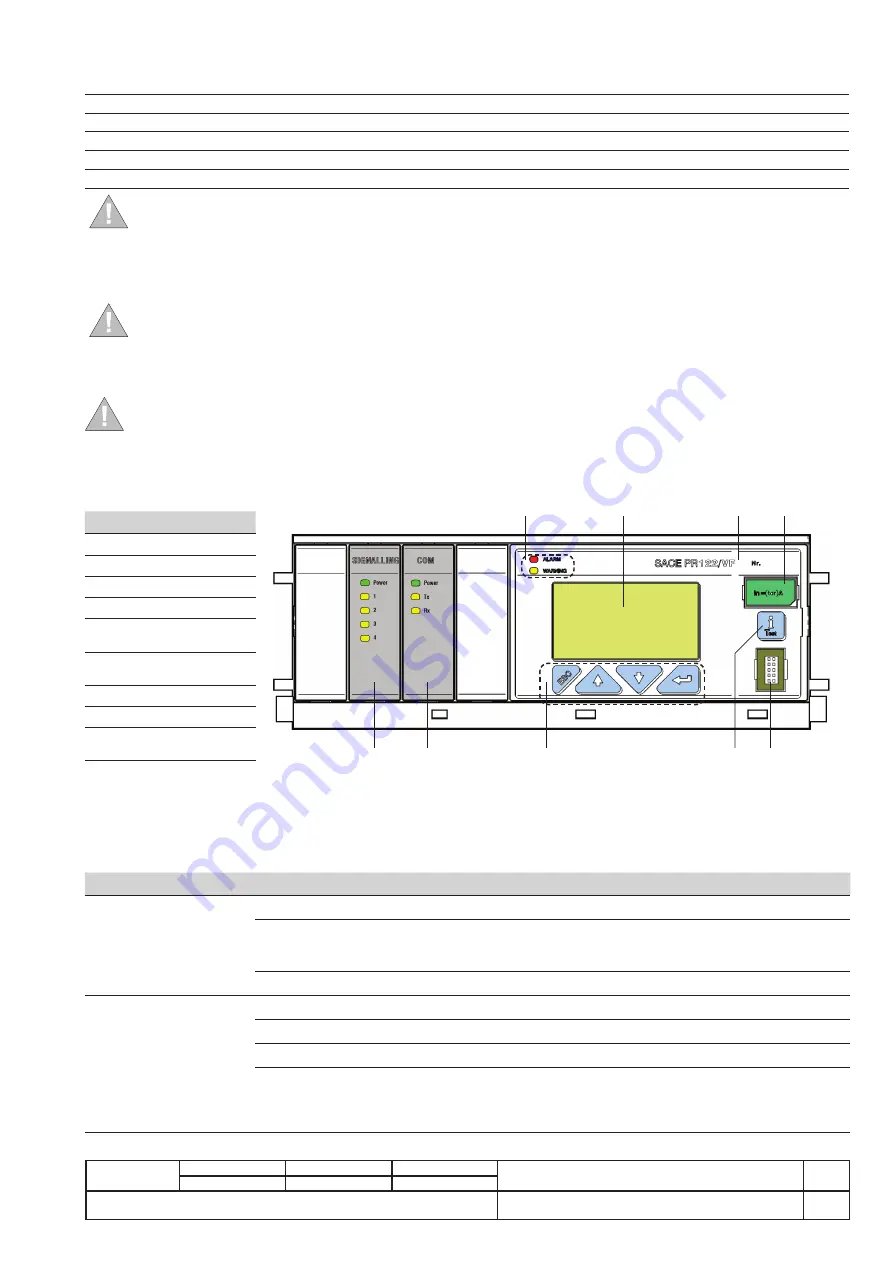
12.2. User Interface
The settings and information regarding PR122/VF are accessible to the user via the local display. The user can access the menu by
using the push buttons on the front of the unit.
Settings and information are also available using external module that allows remote communication.
Ref. Description
1
LED indicators
2
Graphic Display
3
Serial Number
4
Rating Plug
5
Position for PR120/K
module
6
Position for PR120/D-
M module
7
Main Push-buttons
8
iTest push Button
9
Test connector for
external unit
The following is a description of the main charateristics of the user interface.
The optional and external modules are described starting from para.12.4.
12.2.1. LEDs
There are 2 LEDs on the front of the PR122/VF: both LEDs function only with the trip unit turned on, and offer the user simple evidence
of the status of the trip unit and CB.
In the table that follows, descriptions of the main LEDs are related to trip unit turned ON:
LED
Color
Condition
Description
ALARM
Red
OFF
NO Protection ALARM or Timing
ON (Blink @1Hz)
Protection L Timing
Alarm on one or more of: Contact Wear, Temperature
Error on one or more of: Rating Plug, Key Plug, Trip Coil
ON (Fixed)
Internal Error (necessary assistance of ABB)
WARNING
Yellow
OFF
No Alarm or CB Error
ON (Blink @0.5Hz)
Temperature Pre-Alarm
ON (Blink @1Hz)
Temperature Alarm
ON (Fixed)
AUX absent
Prealarm on one or more of: L protection, Contact Wear
Error in one or more of: Configuration, CB status, Harmonic distortion
IW warning
1
5
2
6
3
7
4
9
8


