B2342
Emax VF
38/66
Doc. no.
Model
Apparatus
Scale
Page No
1SDH000909R0001
12.3.1. Main Area
Starting from default page:
Button
Action
Return to default page
UP/ DOWN
CURRENT MEASUREMENTS PAGE
Button UP/DOWN
iTest
(x1) Protection unit Info; (x2) Circuit Breakers info; (x3) Last Trip Info
Button ESC
12.3.2. Menu Area
The Menu Area has a tree structure that allows the management of the settings and information at various levels.
In the Menu area it is possible to move using the UP, DOWN, ENTER, ESC buttons:
- UP and DOWN for selection of the required option/level/value.
- ENTER button to confirm the selection, to enter the next menu level, to confirm the value changed.
- ESC button to abort the selection, to return to the previous level of menu, to abort the value change.
Level 1
Description
Level 2
Description
1. Protections
Protection settings
1.1. L Protections
Set parameters
1.2. I Protections
Enable/disable, and set parameters
1.3. T Protections
Enable/disable Trip
1.4. LC Protections
Set parameters 1, 2, Iw
2. Measure-
ments
Reading of Current Measurements,
Trip and Events history
2.1. Historical
Read Trips, Events Log, Measurements
2.2. Contact Wear
Read value
3. Settings
Managing of trip unit settings,
CB settings,
Optional functions,
Module parameters
3.1.Circuit Breaker
Set Frequency, Unit Installation
3.2. HW trip
Enable/disable function
3.3. Modules
Set parameters
3.4 Data logger
Enable/disable, and set parameters
3.5 Measure store time
Set value
3.6 System
Set Date, Hours, Language, Password
3.7 Display Contrast
Set value
4. Test
Check of CB status,
test of Trip Coil and display
4.1 CB Status
Read CB Status
4.2 Auto test
Perform Display and LEDs test
4.3 Trip Test
Perform Trip Coil test
4.4 COM module
Read CB Status and test Module
4.5 SIGNALLING module
Test Module
5. About
Trip unit information,
CB information
5.1 Protection unit
Read trip unit info
5.2 Circuit Breaker
Read CB info
The following is a description of the mains 2 level in the Menu area.
12.3.2.1. Changing of parameters
In the Menu Area it is possible to modify all the parameters.
To access to change parameters area, it is necessary to use the PW.
WARNING: To change some parameters only the access PW is required (example: DATE change);
Some parameters need the PW to gain access, and also the confirmation by the user: a special box will appear
where it is possible to enter CONFIRM (to finish updating), ABORT ( to delete updating) or MODIFY (for param-
eter modification).
12.3.3. Protections
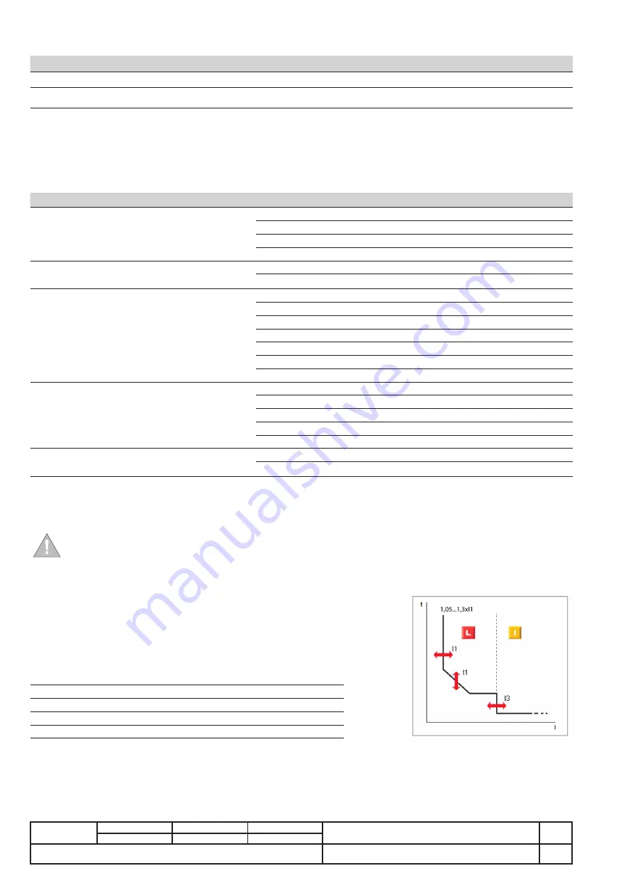
The following is a description of all the protection available to the user in the Protections area:
- Protection against Overload (L protection).
- Protection from instantaneous short-circuit (I Protection).
- Self-protection against over-temperature (T protection).
- Load Control function LC1, LC2, Iw (Load Protection).
The PR122/VF unit manages 4 states depending on main protections threshold
(I
1
, I
3
if ON), and level of primary current (I
f
):
No Alarm: I
f
< 0.9 I
1
The CB remains close.
L Prealarm: 0.9 I
1
< I
f
< (1.05...1.3) I
1
The CB remains close.
L Alarm: (1.05...1.3) I
1
< I
f
< I
3
The CB will open for L protection.
I Alarm: I
f
> I
3
The CB will open for I protection.


