background image

1SDH000909R0001

       B2342

ABB S.p.A.

Via Pescaria, 5
24123 Bergamo - Italy
Tel.: +39 035.395.111

http://www.abb.com

Due to possible developments of standards as well as of 
materials, the characteristics and dimensions specified 
in the present catalogue may only be considered binding 
after confirmation by ABB SACE.

Summary of Contents for B2204

Page 1: ...Emax VF Installation service and maintenance instructions for low voltage air circuit breakers Installation and service instructions 1SDH000909R0001 B2342 ...

Page 2: ...ax ABB SACE Doc no Model Apparatus Dwg Title App Resp Off Take over Off Scale Language EN 1SDH000909R0001 Installation service and maintenance instructions for low voltage air circuit breakers L5712 L6567 B2204 ...

Page 3: ...ions 22 8 4 2 General checks and cleaning 22 8 4 3 Connections between the circuit breaker and the control panel 23 8 4 4 Dismantling the tab cap and arcing chambers 23 8 4 5 Mechanical control 24 8 4 6 Electrical and mechanical accessories 24 8 4 7 Checking contact wear 25 8 4 8 Protection releases 25 8 4 9 Test with Ekip Connect optional 25 8 4 10 Maintenance operations final checks 26 8 4 11 In...

Page 4: ...48 12 6 1 Error Messages 48 12 6 2 Troubleshooting 49 13 Overall dimensions 50 14 Circuit diagrams 57 14 1 Caption 57 14 2 Description of figures 58 14 3 Incompatibilities 58 14 4 Notes 58 B2342 Emax VF 4 66 Doc no Model Apparatus Scale Page No 1SDH000909R0001 ...

Page 5: ...xed part coupled by means of special contacts installed in the fixed part 1 2 External front view of the circuit breaker Fig 1 1 2 3 4 Fixed circuit breaker 1 PR122 VF electronic microprocessor based release 2 Trade mark 3 Operating and control parts of the operating mechanism and release tripped signals 4 Rating plate 1 3 Rating plate 1 3 1 Circuit breaker rating plate Fig 2 E2N VF12 Iu 1200A Ue ...

Page 6: ...Supporting structure made of steel sheet 2 Terminal supporting insulating box 3 Horizontal rear terminals 4a Main fixed contact plates 4b Fixed arcing contact plates 5a Main moving contact plates 5b Moving arcing contact plates 6 Arcing chamber 7 Terminal box for the fixed version Sliding contacts for the withdrawable version 8 Protection release 9 Circuit breaker closing and opening mechanism 10 ...

Page 7: ... and any fixed part on a horizontal surface not in direct contact with the floor but on a suitable support surface Fig 5 The maximum number of stackable circuit breakers is indicated in figure 6 Keep the circuit breaker in the open position and with the closing springs unloaded to avoid unnecessary stresses and the risk of accidents to the person Storage temperature 40 C 70 C Fig 5 Fig 6 With rega...

Page 8: ...zard when you are assembling installing maintaining or removing the circuit breaker from service Some operations must be per formed when the circuit breaker is energized In this case reasonable care and compliance with all safe working practices is required 4 2 Installation of the fixed circuit breaker Fix the circuit breaker to a horizontal surface using the screws M10 x 12 min 4 3 Installation o...

Page 9: ...ure that the head of the screws does not extend more than 5 5 mm from the base of the fixed part 4 4 Installation of the flange on the compartment door Fig 13 Make the compartment door drillings specified in the Overall dimensions paragraph Attach the flange 1 on the front of the compartment door fixing it from the inside by means of the self tapping screws 2 1 2 1 2 3 Fig 12 Note For the E2 E3 fi...

Page 10: ...me as that of the terminal Different connection capacities can be obtained by adjusting the thickness and number of busbars in parallel In some cases reductions in the width of the connection in relation to that of the terminal are allowable as shown in the following examples Vertical terminals Horizontal terminals Circuit breaker Iu A Continuous current carrying capacity Busbar cross section Cont...

Page 11: ...ted in Fig 18 Check tightness after 24 hours Fig 18 M12 high strength screws Tightening torque of the main terminals 70 Nm 2 2 No of screws for phase No of screws for neutral 3 3 5 2 Earthing The fixed circuit breaker and the fixed part of the withdrawable circuit breaker have one or two terminals on the rear marked with the special symbol for connection to earth Fig 9 and Fig 12 Each terminal is ...

Page 12: ... 3 Position contacts 5 4 Conversion of the auxiliary contacts or of the signalling contacts disconnected test isolated connected from normally closed opening to normally open closing or vice versa The contacts are wired at the factory as shown on the electrical circuit diagram If it is necessary to change their state for installation requirements proceed as follows a Auxiliary contacts To access t...

Page 13: ...Page No 1SDH000909R0001 Fig 22 N C contact Sliding contacts N O contact Terminal box b Signalling contacts disconnected test isolated connected To change the state of the position contact proceed in the same way as explained for the auxiliary contacts ...

Page 14: ...nnect voltage to the release Supply the undervoltage release at the corre sponding rated voltage and carry out the circuit breaker closing operation The circuit breaker closes correctly The signals are correct The circuit breaker opens The signal changes over 5 Shunt opening release if any Close the circuit breaker Supply the shunt opening release at the corre sponding rated voltage The circuit br...

Page 15: ...ker connected test isolated and disconnected 10 Seat for the racking in out lever 11 Lever releasing the racking in out operation 12 Key lock on the racking in out operation on request 13 Padlock on the manual closing operation on request 14 Padlock on the racking in out operation on request Fig 23 1 8 2 3 4 6 5 7 1 8 2 3 4 6 5 7 10 11 9 12 14 13 Fixed circuit breaker Withdrawable circuit breaker ...

Page 16: ... springs again when the power returns It is in any case always possible to complete the reloading operation manually c Closing the circuit breaker The operation can only be carried out with the closing springs fully loaded For manual closing press the pushbutton 5 marked with the letter I When there is a shunt closing release the operation can be carried out remotely by means of the special contro...

Page 17: ...tion between the power terminals and WITHOUT coupling the sliding contacts for the auxiliary circuits in this position all electrical operation of the circuit breaker is prevented On the front the indicator 9 Fig 23 indicates DIS CONNECTED Theswitchgearcompartmentdoorcanbeclosed TEST ISOLATED the moving part is inserted in the fixed part WITHOUT any connection between the power terminals but WITH ...

Page 18: ...ial turns the crank handle must oppose no any particular resistance to rotation Should it be necessary to carry out offline circuit breaker operations the crank handle must be removed 12 14 10 9 11 Fig 30 c Passing from the TEST ISOLATED position to the CONNECTED position Make sure that the circuit breaker is open Lower the releasing lever 11 Insert the crank handle in the corresponding coupling 1...

Page 19: ...e program The table shows the maintenance intervals and the frequency of periodical intervention and routine maintenance tasks The following rules should also be followed Even circuit breakers that are little used or remain on or off for long periods should be subject to the maintenance programme The SACE PR122 VF release enable the number of operations performed by the circuit breaker in use to b...

Page 20: ...e equivalent can be used Check that there are no traces of overheating on the terminals This problem is due to discolouring of the contact parts the contact parts are normally silver in colour Check that the bolts fixing the connections to the terminals are tight M12 70Nm WARNING before working on fixed circuit breakers or on fixed part disconnect the supply to the power circuit and to the auxilia...

Page 21: ... PR1 22 V F Fig 36 8 3 7 Protection releases Supply the protection release from a PR030 B battery unit Check that the protection release is working correctly run Trip Test and Autotest for release Use release PR122 VF to check that there are no alarms on the display and via front LEDs Check that the cables are correctly connected to the release modules and to the release if applicable On PR122 VF ...

Page 22: ... or Extracted positions 8 4 Second level maintenance operations 8 4 1 Preliminary operations open the circuit breaker and check that the control springs are unloaded in the case of a withdrawable circuit breaker remove the circuit breaker from the fixed part before working on it WARNING before working on fixed circuit break ers or on fixed part disconnect the supply to the power circuit and to the...

Page 23: ...lver in colour Check the tightness of the bolts fixing the connections to the terminals M12 70Nm WARNING before working on fixed circuit break ers or on fixed part disconnect the supply to the power circuit and to the auxiliary circuits and earth the terminals in a visible manner both on the sup ply and on the load side Check that the connecting screws of the cables of the terminal boards are tigh...

Page 24: ... lubricate with MOBILGREASE 28 EXXON MOBIL the supports of the operating shaft including those on the sides of the circuit breaker see fig 43 part B Check that the opening and closing shafts are free to rotate SACE PR122 VF Fig 43 In the case of deformed or oxidated springs missing rings or serious wear to the controls contact ABB Sace Subject to the customer s approval ABB can replace A type part...

Page 25: ...BB technician 6 1 Check the blowout magnets distances distance A fig 45 Fig 45 Circuit Breaker 6 2 close the circuit breaker and check the gap A If the gap A is not correct contact ABB Sace If the gap A is correct open the circuit breaker and refit the arc chambers Subject to the customer s approval ABB can replace A type parts 8 4 8 Protection releases Supply the protection release with a PR030 B...

Page 26: ...ence Open Springs unloaded Open Springs loaded Closed Springs unloaded Closed Springs loaded Check operation of the accessories if present Check operation of reduction gear if present Check operation of undervoltage release if present Check operation of opening release if present Check operation of closing release if present Check operation of auxiliary contacts of circuit breaker if present Check...

Page 27: ...rating circuit faulty Check connections fuses interlocks protection circuit breakers and consent contacts Screws for clamping loose wires and auxil iary circuits Check tightness of the screws connecting the wires Incorrect electrical connections in the power supply circuit Check the connections with the corre sponding circuit diagram Damaged coil Replace the coil Operating mechanism blocked Operat...

Page 28: ... 380 400 V AC 440 V AC Operating limits CEI EN 60947 2 Standards YO YO2 70 110 Un YC 85 110 Un Inrush power consumption Ps DC 200 W Inrush power time 100 ms AC 200 VA Continuous power Pc DC 5 W AC 5 VA Opening time YO YO2 max 60 ms Closing time YC 60 10 ms Insulation voltage 2500V 50 Hz for 1 min Undervoltage release YU The undervoltage release opens the circuit breaker in the case of a considerab...

Page 29: ...gnalling on the operating mechanism by pushing the trip pushbutton in when the circuit breaker has been opened following tripping of an overcurrent release The circuit breaker can only be closed again by putting the pushbutton back into its normal position included in the standard configuration Reference figure in the electrical circuit diagrams S51 13 b Electrical and mechanical trip signalling f...

Page 30: ...cuit breaker mechanical operations The indication is visible on the front of the circuit breaker from the outside 10 2 Mechanical locks a b Lock in open position Different mechanisms are available which enable the circuit breaker to be locked in the open position These devices can be controlled by a key a a special circular lock with different keys for a single circuit breaker or with the same key...

Page 31: ...of 2 supplies and a bus tie The two half busbars can be supplied by a single transformer bus tie closed or simultaneously by both bus tie open One or two circuit breakers out of three can be closed at the same time D THREE A unit of 3 supplies a single closed circuit break er Three supplies generators or transformers on the same busbar for which parallel operation is not allowed Only one of the th...

Page 32: ...lified and expert personnel only If in doubt about its safe usage the unit must be put out of service to prevent any accidental use You must assume that safe usage is impossible if 1 the unit shows visible signs of damage 2 the unit does not function for example with autotest or with the trip test unit 3 the unit has been damaged in transit WARNING Before putting into service it and or replacing t...

Page 33: ...or protection release TC Trip Coil opening solenoid SW Software i Test i Test button on the front of relay Trip CB opening generated by the release Vaux Auxiliary power supply 11 2 2 Notes A Use the Belden 3105A type two wire cable for instance not supplied by ABB SACE B Use the Belden 3106A type three wire cable for instance not supplied by ABB SACE C The unit has a backup protection function if ...

Page 34: ... Accessory units it is possible to expand the performance information management signals and commands with module PR120 D M it is possible to start remote communication with the unit and to command mechanical accessories as Yo and YC with module PR120 K it is possibile to use external contacts associated to the CB events or status with external unit BT030 USB or Ekip T P it s possible to start tem...

Page 35: ...isplay backlight will be ON only with AUX within required range 12 2 User Interface The settings and information regarding PR122 VF are accessible to the user via the local display The user can access the menu by using the push buttons on the front of the unit Settings and information are also available using external module that allows remote communication Ref Description 1 LED indicators 2 Graph...

Page 36: ...ses below the value is available also the phase of the maximum current shown From the default page by pushing the DOWN or UP button it is possible to access to the CURRENT MEASUREMENTS page with the measurement of all 3 phase currents 12 2 2 2 CB and Trip Unit Error The error messages regarding the trip unit and CB are shown on the bottom left corner of the display Every message except for the ABB...

Page 37: ...vel Aborting change ENTER Into the main menu allow choice of the items Confirm change UP With display on Default page by pushing UP or DOWN buttons it is possible to enter in the Current Ammeter page Move into the menu Change parameters and settings values DOWN WARNING For some parameters with a large range it is possible to hold the button down UP or DOWN to speed up the modifcation of the value ...

Page 38: ...me Set value 3 6 System Set Date Hours Language Password 3 7 Display Contrast Set value 4 Test Check of CB status test of Trip Coil and display 4 1 CB Status Read CB Status 4 2 Auto test Perform Display and LEDs test 4 3 Trip Test Perform Trip Coil test 4 4 COM module Read CB Status and test Module 4 5 SIGNALLING module Test Module 5 About Trip unit information CB information 5 1 Protection unit R...

Page 39: ...tep 0 01s Determines the activation duration of the start up threshold While the I protection is turned OFF only the L protection will operate for all the fault current range While the I protection is turned ON the unit will trip by I protection with If I3 The ttrip for I protection is 60ms The Start up function is enabled disabled from the I protection menu The Start up function enables the prote...

Page 40: ...s the presence or absence of the load LC1 threshold 50 I1 100 I1 step 1 Determines the threshold for LC1 Alarm Threshold 2 Threshold ENABLE DISABLE Determines the presence or absence of the load LC1 threshold 50 I1 100 I1 step 1 Determines the threshold for LC1 Alarm Threshold Iw Threshold ENABLE DISABLE Determines the presence or absence of the Iw threshold 0 3In 10In step 0 05In Determines the t...

Page 41: ...n 1 Trip number the highest number is the last trip 2 Date and time of trip 3 Protection that caused trip 4 Current value during trip By choosing Trip from the Historical menu the last one recorded will be shown To view the other trip details use the UP and DOWN push buttons 12 3 4 2 Events The display shows information about Log events as follows Ref Description 1 Log number the oldest Log is sho...

Page 42: ... possible to read the Contact Wear percentage indicating the percentage of wear on the CB contacts This is just an approximate estimation of the real value of contacts wear 12 3 5 Settings The following is the description of all the parameters and setting available to the user into the Settings area CB Installation and CB nominal frequency Circuit Breaker Set of HW trip function Optional Module PR...

Page 43: ...s are in read only mode except for the setting Local Remote available to user With unit in Local status all parameters and settings are in read only mode WARNING Use the address modbus Standard only 12 3 5 4 Datalogger On this section is possible to set the Datalogger function parameters The data logger function can be used to save the instantaneous values of certain analog and digital measurement...

Page 44: ... the unit New Password 0000 9999 User can change the password WARNING With unit turned OFF for more than 48hours Date will reset and it is necessary to enter a new value incorrect value will be displayed on the bottom part of display WARNING To change Language it is necessary to have CB in OPEN status To change the password it is necessary to confirm the new value twice 12 3 5 7 Display contrast I...

Page 45: ... turned ON 1 report the status of contact 1 LED tuned ON means Contact 1 closed 2 same function of 1 related to contact 2 3 same function of 1 related to contact 3 4 same function of 1 related to contact 4 No LED is used to show the status for Digital input 12 4 2 1 Digital Input The unit enables the digital input to be associated with the following functions outside trip control zeroing release t...

Page 46: ...it is possible to enter an event reaction delay and the latch option with the contact ON once it has been activated it remains switched The contacts can be reset using input or by remote 12 4 3 PR030 B The PR030 B power supply module is an external unit allowing temporary powering of the trip unit It can be used with trip unit turned off to check or change settings parameters and perform CB and tr...

Page 47: ...d with one or more ABB low voltage appliances In particular Ekip Connect supports the connection of ABB automatic low voltage circuit breakers fitted with an electronic trip unit in order to Set up Monitor status Read information alarms measurements parameters Modify configuration parameters above all for trip units which do not feature a display Carry out commands Find faults in the communication...

Page 48: ... 30 12 6 Help 12 6 1 Error Messages If some operations cannot be performed on unit a pop up message is displaedy The following is a description of these messages Error Message Description Password error Session impossible A programming session cannot be started due to a contingency e g a timer controlled delay still elapsing Value outside range Value beyond the established limits Exception 6 Comma...

Page 49: ...ing and the buffer capacitor is discharged FN if more than 48h has elapsed 10 The password is not requested The password has been disabled FN re enter the password with a value other than 0000 11 Impossible to change any parameter from display menu 1 PR122 VF in alarm situation 2 Unit in Remote configuration 1 FN 2 FN 12 Temp sensor or Start up message Possible failure inside trip unit Contact ABB...

Page 50: ...zontal rear terminals A B C D E E2 296 148 26 114 117 5 E3 404 202 26 114 117 5 A A B B C C C C D D E E Legend 1 Inside edge of compartment door 2 Segregation where foreseen 3 Circuit breaker M10 fixing drilling use M10 screws 4 N 1 M12 screw E2 E3 for earthing included in the supply 5 Insulating or metal insulated wall E2 View A E3 View A ...

Page 51: ...342 Emax VF 51 66 Doc No Model Apparatus Scale Page No 1SDH000909R0001 E2 E3 Fixed circuit breaker Basic version with vertical rear terminals E2 View A E3 View A Captive M12 included in the supply Fig 36a ...

Page 52: ...he main terminals Nm 70 Tightening torque of the earthing screw Nm 70 Compartment dimensions Compartment door drilling High resistance M12 screw Quantity for terminal PHASE N 2 holes for IP54 protection Depth 3 POLES Fixed circuit breaker Fig 39 Holes for passing through flexible cables for mechanical interlocks ...

Page 53: ... rear terminals E2 View A E3 View A A B Fig 40 Legend 1 Inside edge of compartment door 2 Segregation where foreseen 3 Fixing fixed part Ø 10 drilling use M8 screws 4 N 1 M12 screw E2 E3 for earthing included in the supply 5 Run from connected for a TEST to isolated 6 Alternative drilling with 25mm pitch for fixing fixed part 7 Ventilation drilling on the switchgear ...

Page 54: ... Emax VF 54 66 Doc no Model Apparatus Scale Page No 1SDH000909R0001 E2 E3 Withdrawable circuit breaker Basic version with vertical rear terminals Captive M12 included in the supply E2 View A E3 View A Fig 42 ...

Page 55: ...que of the fixing screws 20 Nm Tightening torque of the main terminals 70 Nm Tightening torque of the earthing screw 70 Nm Compartment dimensions Compartment door drilling High resistance M12 screw Quanty per terminal PHASE N 2 holes for IP54 protection Depth Fig 46 Holes for passing through flexible cables for mechanical interlocks ...

Page 56: ...c no Model Apparatus Scale Page No 1SDH000909R0001 E2 180 E3 234 Fixed version Withdrawable version Minimum distance between the circuit breaker and the switchgear wall Door drilling Compartment door mechanical lock Fig 47 A ...

Page 57: ...release with communication module PR120 D M K51 YO Opening control from PR122 VF electronic release with communication module PR120 D M M Motor for loading the closing springs Q Circuit breaker Q 1 27 Circuit breaker auxiliary contacts S33M 1 3 Limit contacts for spring loading motor S43 Switch for setting remote local control S51 Contact for electrical signalling of circuit breaker open due to tr...

Page 58: ...the following figures cannot be supplied simultaneously on the same circuit breaker 6 7 8 13 14 22 46 47 14 4 Notes A The circuit breaker is only fitted with the accessories specified in the ABB SACE order acknowledgement Consult the tech nical catalogue for information on how to make out an order B The undervoltage release is supplied for operation using a power supply branched on the supply side...

Page 59: ... 3 14 3 26 Standards Shield may be drawn in any shape Time delay Mechanical or electrical connection Manual mechanical control general case Rotating control Pushbutton control Equipotentiality Terminal Plug and socket male and female Motor general symbol Current transformer Voltage transformer Winding of three phase tran sformer Star connection Change over position con tact with momentary circuit ...

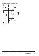
Page 60: ...Apparatus Scale Page No 1SDH000909R0001 Circuit diagram Operating status Three pole circuit breaker with PR122 VF electronic release B1E B1I XK11 1 2 A1I A1E 1 2 1 c1 b1 a1 XO XO Q B1 C1 2 XK10 K51 1 Y01 2 A1 PR122 VF C1I C1E 1 2 XK12 ...

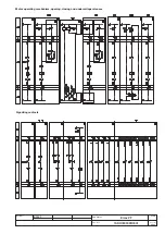
Page 61: ...B2342 Emax VF 61 66 Doc No Model Apparatus Scale Page No 1SDH000909R0001 Motor operating mechanism opening closing and undervoltage releases Signalling contacts ...

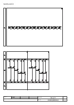
Page 62: ...B2342 Emax VF 62 66 Doc no Model Apparatus Scale Page No 1SDH000909R0001 Signalling contacts ...

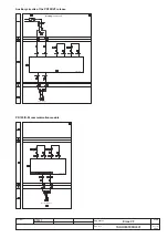
Page 63: ... Emax VF 63 66 Doc No Model Apparatus Scale Page No 1SDH000909R0001 W1 SYSTEM BUS PR122 VF PR120 D M communication module W2 L OCAL BUS PR122 V F Auxiliary circuits of the PR122 VF release Warning see note F ...

Page 64: ...B2342 Emax VF 64 66 Doc no Model Apparatus Scale Page No 1SDH000909R0001 PR122 VF PR122 VF PR120 K signalling module ...

Page 65: ......

Page 66: ...123 Bergamo Italy Tel 39 035 395 111 http www abb com Due to possible developments of standards as well as of materials the characteristics and dimensions specified in the present catalogue may only be considered binding after confirmation by ABB SACE ...

Reviews: