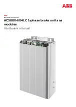


Single-line diagram of the drive system
The diagram below shows a typical common DC link drive system.
1
2
3
4
6
5
6
8
9
10
11
7
M
M
AC supply
1
Input (AC) fuses
2
Supply unit
3
DC link
4
Inverter DC fuses
5
Inverter units. In this example, one of the units ocnsists of two inverter modules connected in parallel
6
Brake chopper DC fuses
7
Attenuator. Suppresses voltage spikes at chopper input. Must be installed if it is possible to disconnect
all inverter units from the DC link with the supply unit on, otherwise optional.
8
Brake chopper
9
Brake resistors
10
Motors
11
Operation principle and hardware description 15
Summary of Contents for ACS880-604LC
Page 1: ... ABB INDUSTRIAL DRIVES ACS880 604LC 1 phase brake units as modules Hardware manual ...
Page 2: ......
Page 4: ......
Page 12: ...12 ...
Page 20: ...20 ...
Page 33: ...Overview of kits Mechanical installation 33 10 ...
Page 34: ...Stage 1 Installation of common parts 34 Mechanical installation ...
Page 35: ...Stage 2 Installation of mounting plate Mechanical installation 35 10 ...
Page 36: ...Stage 3 Installation of cooling components 36 Mechanical installation ...
Page 37: ...Stage 4 Installation of brake module and attenuator Mechanical installation 37 10 ...
Page 40: ...40 ...
Page 58: ...58 ...
Page 64: ...64 ...
Page 82: ...82 ...
Page 84: ...Brake chopper module NBRW 669 84 Dimension drawings ...
Page 85: ...Attenuator Dimension drawings 85 ...
Page 86: ...Brake resistor 234 300 1320 Ø 7 345 R R 1270 86 Dimension drawings ...
Page 88: ...88 ...
Page 102: ......


