Terms and abbreviations
Description
Term
Conducts the surplus energy from the intermediate circuit of the drive to the brake
resistor when necessary. The chopper operates when the DC link voltage exceeds a
certain maximum limit. The voltage rise is typically caused by deceleration (braking)
of a high inertia motor.
Brake chopper
Brake chopper enclosed in a metal frame or housing. Intended for cabinet installation.
Brake chopper module
Dissipates the drive surplus braking energy conducted by the brake chopper to heat
Brake resistor
Brake chopper modules under control of one control board, and related accessories
Brake unit
One section of a cabinet-installed drive. A cubicle is typically behind a door of its own.
Cubicle
DC circuit between rectifier and inverter
DC link
Frequency converter for controlling AC motors
Drive
Electromagnetic compatibility
EMC
Insulated gate bipolar transistor
IGBT
DC circuit between rectifier and inverter
Intermediate circuit
Converts direct current and voltage to alternating current and voltage.
Inverter
Drive for controlling several motors which are typically coupled to the same machinery.
Includes one supply unit, and one or several inverter units.
Multidrive
Brake chopper control board
NBRC
Series of optional, liquid-cooled brake chopper modules
NBRW
In the drive control program, user-adjustable operation instruction to the drive, or signal
measured or calculated by the drive.
In some (for example fieldbus) contexts, a value that can be accessed as an object,
eg, variable, constant, or signal.
Parameter
Converts alternating current and voltage to direct current and voltage
Rectifier
Series of brake resistors
SAFUR
Introduction to the manual 11
Summary of Contents for ACS880-604LC
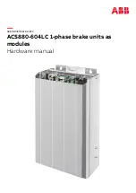
Page 1: ... ABB INDUSTRIAL DRIVES ACS880 604LC 1 phase brake units as modules Hardware manual ...
Page 2: ......
Page 4: ......
Page 12: ...12 ...
Page 20: ...20 ...
Page 33: ...Overview of kits Mechanical installation 33 10 ...
Page 34: ...Stage 1 Installation of common parts 34 Mechanical installation ...
Page 35: ...Stage 2 Installation of mounting plate Mechanical installation 35 10 ...
Page 36: ...Stage 3 Installation of cooling components 36 Mechanical installation ...
Page 37: ...Stage 4 Installation of brake module and attenuator Mechanical installation 37 10 ...
Page 40: ...40 ...
Page 58: ...58 ...
Page 64: ...64 ...
Page 82: ...82 ...
Page 84: ...Brake chopper module NBRW 669 84 Dimension drawings ...
Page 85: ...Attenuator Dimension drawings 85 ...
Page 86: ...Brake resistor 234 300 1320 Ø 7 345 R R 1270 86 Dimension drawings ...
Page 88: ...88 ...
Page 102: ......


