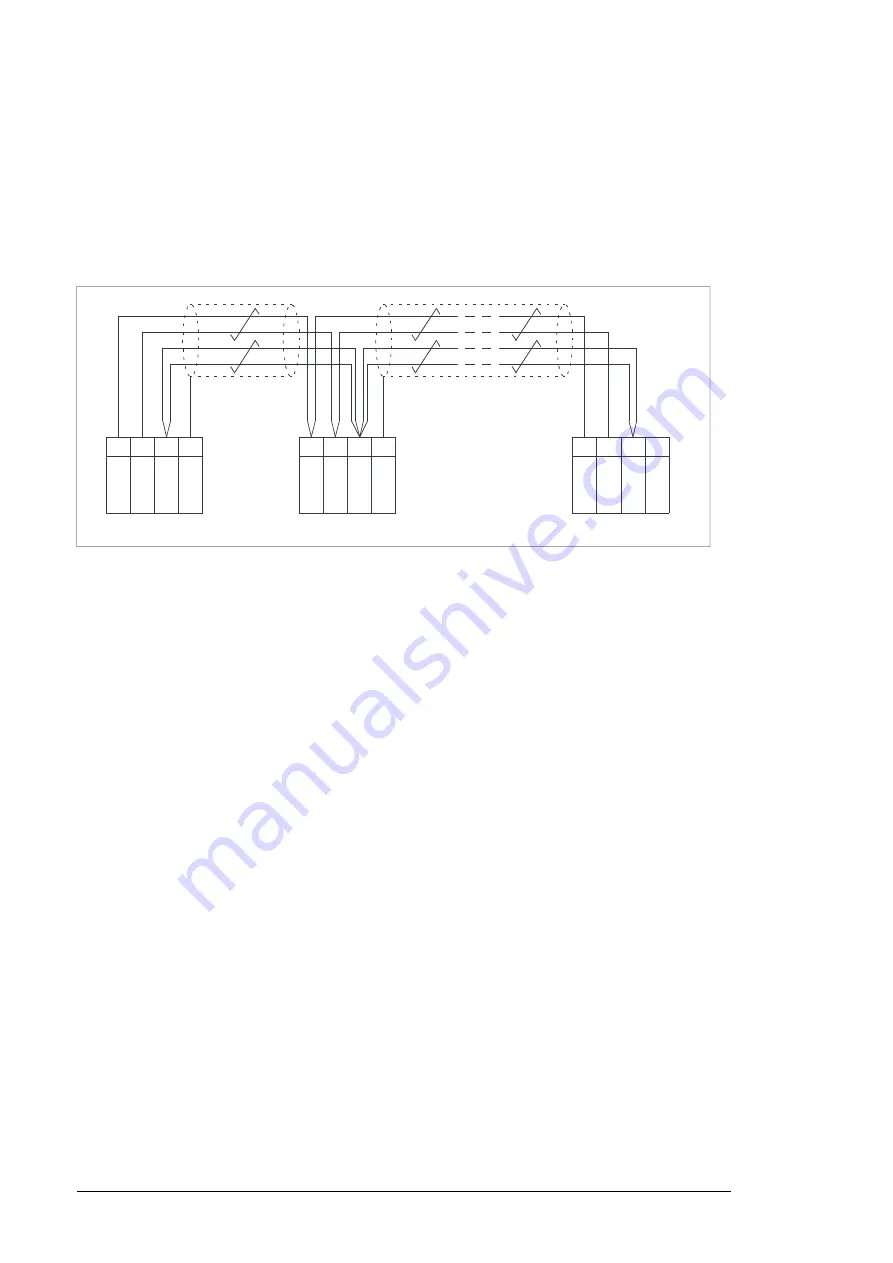
Enable bus termination on the inverters at the ends of the drive-to-drive link by setting switch
D2D TERM on the control unit to ON. On intermediate inverters, disable bus termination.
Use shielded twisted-pair cable (~100 ohm, for example, PROFIBUS-compatible cable) for
the wiring. For best immunity, high quality cable is recommended. Keep the cable as short
as possible; the maximum length of the link is 50 meters (164 ft). Avoid unnecessary loops
and running the cable near power cables (such as motor cables). Ground the cable shields.
The following diagram shows the wiring of the drive-to-drive link.
1
2
3
4
B
A
BGND
SH
IE
L
D
XD
2
D
1
2
3
4
B
A
BGND
SH
IE
L
D
XD
2
D
1
2
3
4
B
A
BGND
SH
IE
L
D
XD
2
D
Termination ON
Termination ON
Termination OFF
■
Safe torque off (XSTO, XSTO OUT)
On the inverter control unit (A41), the XSTO input can be used to implement a safe torque
off (STO) function. For the drive to start, both connections (OUT1 to IN1 and IN2) must be
closed. By default, the terminal block has jumpers to close the circuit. Remove the jumpers
before connecting an external Safe torque off circuit to the drive.
For information on the implementation of a Safe torque off function, see chapter
torque off function (page 189)
Note:
The XSTO input only acts as a true Safe torque off input on the inverter control unit [A41].
De-energizing the IN1 and/or IN2 terminals on the supply control unit [A51] will stop the
supply unit but not constitute a true safety function.
The XSTO OUT connector is wired to the STO IN connector of one inverter module. In case
the inverter unit consists of multiple modules, the STO OUT connector of the first module
is wired to the STO IN connector of the next module etc. so that all modules are part of the
chain.
■
FSO-xx safety functions module connection (X12)
Not in use at the time of publishing.
■
SDHC memory card slot
The BCU-x2 has an on-board data logger that collects real-time data from the power modules
to help fault tracing and analysis. The data is stored onto the SDHC memory card inserted
into the SD CARD slot and can be analyzed by ABB service personnel.
112 Control units of the drive
Summary of Contents for ACS880-07CLC
Page 1: ...ABB industrial drives Hardware manual ACS880 07CLC drives ...
Page 2: ......
Page 4: ......
Page 64: ...64 ...
Page 82: ...82 ...
Page 91: ...PE PE 10 13 12 22 Electrical installation 91 ...
Page 122: ...122 ...
Page 124: ...124 ...
Page 132: ...5 4 11 7 6 8 132 Maintenance ...
Page 133: ...14 15 16 12 13 17 Maintenance 133 ...
Page 141: ...5 Set the real time clock Maintenance 141 ...
Page 142: ...142 ...
Page 150: ...150 ...
Page 176: ...ACS880 07CLC 0390A 7 C121 marine construction 176 Dimensions ...
Page 177: ...ACS880 07CLC 1310A 7 Dimensions 177 ...
Page 178: ...ACS880 07CLC 2180A 7 C121 marine construction 178 Dimensions ...
Page 179: ...ACS880 07CLC 3260A 7 C121 marine construction Dimensions 179 ...
Page 181: ... 2 D8D Dimensions 181 ...
Page 182: ... 3 D8D 182 Dimensions ...
Page 183: ... 4 D8D Dimensions 183 ...
Page 185: ...Inverter module cubicle with two R8i modules bottom cable exit Dimensions 185 ...
Page 186: ...Inverter module cubicle with three R8i modules bottom cable exit 186 Dimensions ...
Page 187: ...Brake chopper cubicle D150 Dimensions 187 ...
Page 188: ...188 ...
Page 202: ...202 ...
Page 211: ......
Page 212: ......
Page 214: ...Contact us www abb com drives 3AXD50000131457 Rev A EN EFFECTIVE 2018 03 09 3AXD50000131457A ...


